Introduction
This repair guide was authored by the iFixit staff and hasn’t been endorsed by Google. Learn more about our repair guides here.
Follow this guide to replace the motherboard on a Google Pixel 4a.
The unreinforced display panel on the Pixel 4a is fragile. Pay special attention to the warnings in the opening procedure if you are reusing the screen.
Ce dont vous avez besoin
-
-
Insert a SIM eject tool, bit, or straightened paper clip into the SIM tray hole.
-
Press directly into the hole to eject the SIM card tray.
-
Remove the SIM card tray.
-
-
-
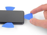
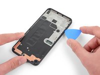
Take note of the two seams on the edge of the phone:
-
Screen seam: This seam separates the screen from the rest of the phone. This is where you should pry.
-
Frame seam: This is where the plastic frame meets the back cover. It is held in place by screws. Do not pry at this seam.
-
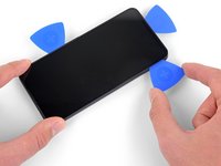
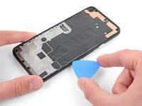
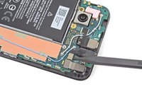
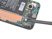
Before you begin, note the following areas on the screen:
-
Screen flex cable: Do not insert the opening pick deeper than instructed or you risk damaging this cable.
-
Adhesive perimeter: Prying beyond this narrow perimeter without angling the pick will damage the OLED panel.
Coll down guys and gals.
1) go below the Display and not between the backcover/middle (see the other comments)
2) just take care about the flex/display cable position (which is iirc about on the middle i.e. 2nd 3rd from the bottom ON THE LEFT side dear OP)
Everything else is just separting the glued on Display from the Phone.
See the other comments
Cool down guys and gals.
1) go below the Display and not between the backcover/middle (see the other comments)
2) just take care about the flex/display cable position (which is iirc about on the middle i.e. 2nd 3rd from the bottom ON THE LEFT side dear OP)
Everything else is just separting the glued on Display from the Phone.
See the other comments
I've measured it: The cable starts arround 1.4-1.6 cm from the lower half from the bottom on the left side.
So You can cut the bottom left corner and of course the upper left one but for safety's sake, watch out for the camera.
You can go up to 5cm down from the upper left side till You're near the cable.
When you say left side, is this your left when the phone screen is facing you?
jaunie -
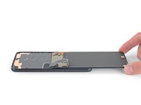
The third image her shows the back of the screen, not the body of the phone
I wanted to add yet another warning: Be extremely careful in the lower left edge of the screen!
I tried to be gentle, and inserted the pick very little, but still, after reassembly, my screen remained black (while the rest of the device continued working – if you have USB debugging enabled, you can still use it using the
scrcpytool). There was no visible damage; I suspect that I damaged the ribbon cable in the lower left in an invisible way.A new screen fixed the problem. Still, this increased the cost of repair by ~$100. I think the guide should highlight the danger even more. Please be careful – one guide on YouTube I found afterwards avoids inserting the pick in the lower left corner entirely, and just "wiggles it free".
-
-
-
Apply a heated iOpener to the right edge of the display for one minute to soften the adhesive.
I did the boiling water method. 3 min in water worked fine. I applied to right side and left side for 90 seconds
EN : Heat is definitely not the best way here. I have tried the iOpener and my hot air station to no avail.
Best way is to use a plastic dropper and apply a few drops of isopropyl alcohol. The dropper is definitely the most useful tool of the battery fix kit to remove all the adhesive precisely and without damaging anything.
FR : Chauffer n'est clairement pas la meilleure méthode ici. J'ai essayé l'iOpener et ma station à air chaud en vain.
La meilleure méthode est d'utiliser une pipette en plastique et d'appliquer quelques gouttes d'alcool isopropylique. La pipette est clairement l'outil le plus utile du fix kit batterie pour enlever précisément tout l'adhésif sans rien endommager.
2. Dissolving the adhesive: the i-opener makes a pretty good neck-warmer but I found it useless as a way to dissolve the adhesive; I tried 8 times before giving up and going to a heat gun. (It doesn't help the documentation has only a few sentences on how to do this most critical step.)
2a. You need a procedure to confirm the adhesive has dissolved other than pulling on the suction cup and likely causing damage to the screen.
2b. Recommendation: Get rid of the i-opener and instead provide full details on how to safely use a heat gun, hair dryer or heating pad to dissolve the adhesive on all 4 sides. Also show how to safely confirm all the adhesive dissolved
-
-
-
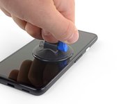
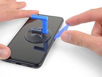
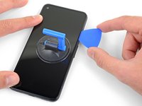
Place a suction cup as close to the right edge of the screen as possible.
-
Lift the suction cup with a strong steady force.
-
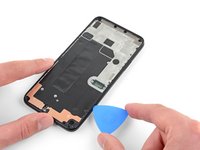
Insert the tip of an opening pick into the screen seam no more than 1 mm.
It's pretty easy. Insert it just below the screen between the Display and the Display “holder” or mold.
I highly recommend not using the mediator that is too thick and too rigid, as the screen is super fragile. Instead, I used a piece of X-ray film. It's thinner, more flexible, and sharper, making it easier to cut through the adhesive along the screen.
I followed your advice and it's working great, i just cut some small piece of a X-ray film I had and after some heating it's easy to cut the adhesive, I just used the mediator to hold it opened
EN : I bought the anti-clamp for this step because I was scared to break my screen but I finally ended up using the suction cup delivered in the battery fix kit which is way more simple to use and it's easier to see when you lift the screen.
Place the suction cup exactly as shown then apply a few drops of isopropyl alcohol into the screen seam next to the suction cup. Once the adhesive is soaked with alcohol, you should be able to lift the screen with the suction cup really easily. Then insert the opening pick or a thin plastic card under the screen.
FR : J'ai acheté l'anti-clamp pour cette étape car j'avais peur de péter mon écran mais finalement j'ai utilisé la ventouse fournie dans le fix kit batterie qui est bien plus simple à utiliser et on voit mieux quand on soulève l'écran.
Placez la ventouse exactement comme indiqué puis appliquez quelques gouttes d'alcool isopropylique dans la jointure de l'écran juste à côté de la ventouse. Une fois que l'adhésif est imbibé d'alcool, vous devriez pouvoir soulever l'écran avec la ventouse très facilement. Puis insérez le médiator ou une fine carte en plastique sous l'écran.
3. Removing the screen: Your approach of just dissolving the adhesive on one side then using picks cut out the other 3 sides exposes the screen to excess stress.(again the documentation provides almost no detail on how set the suction or how to hold the phone to avoid screen damage.)
3a. The picks are too thick, too stiff and result in a lot of pushing and prying. The kit should contain a specific adhesive cutting tool
-
-
-
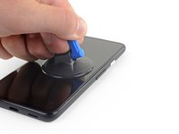
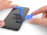
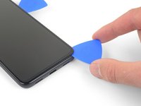
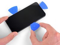
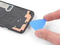
With the pick 1 mm into the gap, pivot the pick upwards to a steep angle.
-
At a steep angle, carefully push the pick into the gap about 1/4 inch (6 mm). The pick should slide in below the OLED panel.
This took me a while, I ended up sharpening the tip of the pick with a razor so I could push it through the seam and slicing a few times, heat->sharpen-> slice until I finally got it to move, and once it slid under carefully heated up areas and sliced with ~2mm of the pick.
Thanks for this tip, I also shaved down my initial pick and that (plus several rounds of reheating and re-trying) eventually got me there!
This sounds also harder than it is. Push it in 1mm and just lift the other end in a wider angle like 70° degree from the horinzontal position. There “shouldn't” be much you can do wrong. Because except for the Data cable (flex) at a certain position, I can't remeber anything important but isolating tapes that I have scratched.
It's just the Screen glued to the mold. That's it.
Oh, and I wonder here where do You all get such thins plectrums? I have also the flat plastic version and the thin plastic cards but none of them were thin enough for this!!
I ended up using the backside i.e. the dull side of a Razorblade. I didn't saw any alternatives to this. Did You hear this OP?
Any!!
the display flex is directly on the bottom of the phone. BE VERY CAREFUL when going around the bottom to not hit the display flex!!!
Be very, VERY careful when inserting the pick or whatever you're using. That OLED panel is super fragile. When I was replacing the battery, I damaged my screen and had to replace it, as well. The new screen worked, thankfully. I tried to be very careful but somehow still damaged the screen. I couldn't detect any damage to the screen except there was a very small fleck of the iridescent material. That's the only thing I could tell.
FYI: The phone would boot up into SOME kind of mode. I could feel it vibrate when I held down the power button or used the fingerprint sensor. If you're in that position, it's a good chance a new screen will get your phone up and running. At least, that was the case for me.
-
-
-
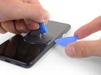
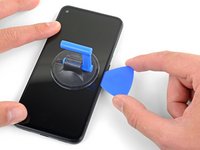
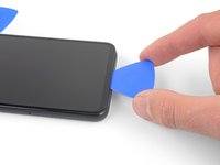
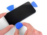
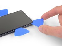
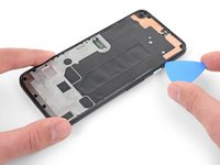
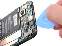
Slide the pick along the right edge of the screen to cut the adhesive.
-
Leave the pick in the top right corner to prevent the adhesive from re-sealing.
The display flex is directly on the bottom of the phone. Be very careful when goign around the bottom to not hit the display flex!!!
-
-
-
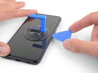
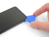
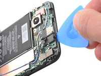
Insert another opening pick into the right edge of the phone at an angle where a gap has already formed to prevent damage to the OLED panel.
-
Slide the opening pick around the bottom of the phone to cut the adhesive.
-
Leave the pick inserted along the bottom edge to prevent the adhesive from resealing.
Top and bottom edge adhesive were much stronger than this suggests. Corners were very hard to detach. I killed my screen b/c I cracked it at the top. Worked better with heating around whole perimeter like an iPhone.
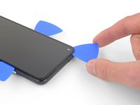
WARNING: Be very careful prying the bottom left and right corners! In fact do not insert anything there because there is only a 0.8mm clearance between the screen and the edge, and there's a 0.5mm space between the screen and front glass where if you insert a pick between the screen will crack and break! I had to replace the screen after only doing a battery repair...
Unfortunately I did not properly read the comments here. So for the unafraid people like me:
DO NOT insert something into the bottom right! Especially not like it is shown in the image at this location!
Instead I suggest start releasing the screen from right, then left side, then top and as the last step release the bottom, but start with the left corner. Do not pry too much and use a bit more heat as suggested.
There is a small image of this critical right corner in Step 16 (the part at the top is the display and the left corner at the top is the critical right corner here). You'll see the orange cable in the corner which is easy to damage...
I can second the warnings - especially at the lower corners the OLED screen is extremely sensitive to breaking - as has happened in my attempt when inserting the pick 2 mm.
The display flex is directly on the bottom of the phone. Be very careful when goign around the bottom to not hit the display flex!!!
Unfortunately despite being very delicate on the bottom right corner I ripped off a tiny bit of the digitizer cable and that resulted in a not working screen... went from spending 50€ for a battery replacement to a 150€ total expense battery + screen... :-( My advice is to not even pry the bottom corner, pry all around, then apply heat carefully until the screen is detaching.
Don't listen to the advice that you don't need to reheat. The bottom corners are very strong and you absolutely don't want to go in more than 1 mm to avoid cutting the display flex. Proceed as follows:
1. Heat and get a pick into the right side (more than 1 mm is never needed, in my case the picks all stayed angled upwards while I did the cutting)
2. Put another pick in right away in the same spot
3. Immediately heat the top corner
4. Move one of the picks towards the top corner cutting all adhesive and let it rest there
5. Heat the bottom right corner
6. Move the other pick to the bottom right corner cutting adhesive (not more than 1 mm, make sure to angle the pick sideways!!)
7. Put another pick in on the right side and move it to the bottom too
8. Heat the bottom and bottom-left corner
9. Very carefully move the first bottom pick around the corner and cut everything on the bottom side
10. Don't insert any new picks on the bottom, always go around the corners with an existing pick
11. Go around the bottom-left corner
12. Insert a new pick on the left side once there is a gap and cut the rest
Do not even try to insert anything on the right corner. I pulled screen upwards fine without touching that corner. Just heat both sides and insert picks everywhere but that corner. Although be extra careful with 5 cm from top to bottom on the left side, there is also a cable there, although not that easy to brake as the one on the right bottom corner. I managed to replace battery successfully like that
I broke the display because I didn't read this comments.
Don't slide into the bottom left and right corners!
I wanted to add yet another warning: Be extremely careful in the lower left edge of the screen!
I tried to be gentle, and inserted the pick very little, but still, after reassembly, my screen remained black (while the rest of the device continued working – if you have USB debugging enabled, you can still use it using the
scrcpytool). There was no visible damage; I suspect that I damaged the ribbon cable in the lower left in an invisible way.A new screen fixed the problem. Still, this increased the cost of repair by ~$100. I think the guide should highlight the danger even more. Please be careful – one guide on YouTube I found afterwards avoids inserting the pick in the lower left corner entirely, and just "wiggles it free".
EN : Do not apply heat, just buy a bottle of isopropyl alcohol. Corners are indeed harder to unglue so apply a few more drops of alcohol and it should be easy.
FR : Ne chauffez pas, achetez une bouteille d'alcool isopropylique. Les coins sont effectivement plus durs à décoller donc appliquez un peu plus d'alcool et ça devrait être facile.
I also broke my screen at this stage. EUR 50 and 2 hours lost
-
-
-
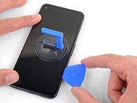
Insert another opening pick into the bottom edge of the phone at an angle where a gap has already formed to prevent damage to the OLED panel.
-
Use the pick to slice through the left edge of the phone.
-
Leave the pick inserted along the left edge of the phone to prevent the adhesive from re-sealing.
The display flex is directly on the bottom of the phone. Be very careful when goign around the bottom to not hit the display flex!!!
-
-
-
Insert another opening pick into the left edge of the phone at an angle where a gap has already formed to prevent damage to the OLED panel.
-
Slide the pick around the top edge of the phone to cut the adhesive.
The display flex is directly on the bottom of the phone. Be very careful when goign around the bottom to not hit the display flex!!!
-
-
-
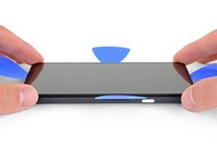
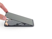
Once you have cut around the perimeter of the phone, carefully lift the right edge of the screen, opening the phone like a book.
-
Use an opening pick to carefully cut through any remaining adhesive.
When I was doing this I found the corners especially the bottom right corner was very glued on!! There are very sensitive cables here and I found part of the old screen's cables (it might not matter if you're replacing the entire screen anyways) were glued onto the phone frame. I came really close to tearing mine, but I saw another review about reapplying heat to get this part loose.
-
-
-
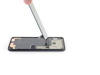
Lift from the top edge and swing the screen over the bottom edge until you can rest it glass-side down.
FR : Précision : La nappe a un bout d'adhésif sur la structure du téléphone, il faut bien faire attention de le décoller. Je viens de tuer la nappe de mon écran qui était fonctionnel...
EN : Advice : The ribbon cable is fixed to the structure with a small piece of adhesive. It should be remove prior to anything else. I just killed the ribbon cable of my perfectly used to work screen...
On reassembly: this is where you peel off the colored part of the adhesive strips, and make sure to put your speaker mesh (if it's not attached to the screen) back in place. It should rest flat-side-down on the frame over the two horizontal indents in the frame edge, at least it should if I did it right ;)
If you are afraid of putting stress on the cable by laying the screen down you can just proceed to next steps while grabbing the screen. I did it like that
-
-
Outil utilisé dans cette étape :Tweezers$4.99
-
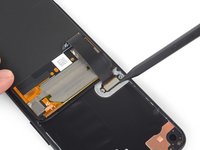
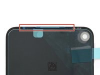
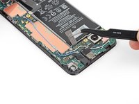
Use a pair of tweezers to carefully peel up the black tape covering the screen connector bracket.
How critical is the tape that covers this connector? I realized upon sealing back up my device that I forgot to re-install it. I imagine it mostly is there to prevent dust and moisture ingress?
Did anything bad happen with yours? I just did the same thing now
Interestingly this tape was missing in my phone. Maybe that explains some of the display issues I occasionally had, like a thin green line on the right side of the screen which could be "pushed" away.
I think I ripped off the cable because it is undistinguishable from the tape! How screwed am I?
Don't bother trying to save the tape. More hassle than it is worth. Just replace with electrical tape
-
-
Outil utilisé dans cette étape :Magnetic Project Mat$19.95
-
Use a T3 Torx driver to remove the two 2.1 mm screws securing the screen connector bracket.
A T4 driver worked for me here.
It is definitely a T4.
Funny ... For me, it was T3. The screws must vary across different phones
T3 worked for me also
-
-
-
-
Use the tip of a spudger to pry up and disconnect the screen flex cable.
No, why the tip? Use the other flat side that doesn't concetrate all the power on one point and Youre doing a propper job.
Only the tip is needed to lift a bit one of the sides and it will pop out. No pressure/power!
-
-
-
Remove the screen.
-
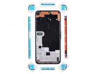
Check if your replacement screen has speaker mesh and top edge adhesive pre-installed.
-
If it does, you won't need the top edge adhesive.
-
If it doesn't, remove the larger clear liner from the top edge adhesive and apply it to the screen (not the frame). Make sure the larger cutout lines up with the speaker mesh.
-
Follow this guide to apply the custom-cut adhesive.
This step seems to imply that a screen replacement is necessary when replacing the charging port. Is the charging port replaceable without replacing the screen? I understand great care must be taken not to damage the original screen in the procedure, but can it be reinstalled?
Yes, it can be reinstalled.
Just a heads up: If you are like me and you have accidentally turned on your Pixel 4a at some point while trying to pry the screen, don't worry too much. I was able to just connect my display with the device on. Nothing will happen until you reboot, and then the screen will initialize.
It would help to add that the new screen is reattached after adding glue to phone body, not the screen. With the iFixit screen adhesive pieces, a guide to which piece goes where would help also. For that I used this picture: Google Pixel 4a Display Adhesive - Genuine. Yet that is not enough as there is a cover for (speaker?) which is not clear how to apply that.
The repair kit comes with Google Pixel 4a Display Adhesive - Genuine but there is no guide on how to apply that adhesive. I sent an email, but Ifixit won't make an instruction page for this.
To explain how the adhesive sold by iFixit works, the actual adhesive is the black strip which is held between two pieces of plastic. Line up the pieces with the clear plastic side down. Note that some pieces may be stuck in the box they came in, the plastic is staticky. I recommend that before attaching the new screen you put each piece in place. Remove the clear plastic and place the pieces in place with the colored plastic facing up. The goal is to have the black adhesive strip on the little ledge between the edge and the depression inside the phone. It's the place where you hopefully spent time cleaning out the original adhesive. Place the corners first, then the edges. Press them into place carefully. Before removing the colored plastic attach the phone screen cable and secure it. REMEMBER TO PLACE THE ELECTRICAL TAPE OVER THE CONNECTOR (I forgot to). Then remove the colored plastic, leaving behind the adhesive, and push the screen into place.
Of note: the seal peace at the top goes under the speaker screen, and the seal looks at first like it is reversed. To install that one accurately adhere it to the Screen itself not the body of the phone. align it where there is a see through circle along the seam and a hole in the adhesive. the sealant should run below the speaker screen. When readhering the screen to the body, remove the plastic guides around the body, then last the seal on the screen and align and install.
Super, c'est vraiment à la portée de tout le monde, il faut juste un peu de patience et d'audace.
Je viens de réussir le remplacement de mon écran et c'est impec !
Il n'y a que sur la première partie, où il faut insérer le médiateur, que ça a été compliqué pour moi. Impossible de l'insérer du côté des boutons (à droite donc), par contre quand je me suis décidée à tester en passant par l'autre côté, c'est venu tout seul.
Aussi il m'a fallu un certain temps pour comprendre que sur les adhésifs, seul le trait noir colle, et c'est donc à lui qu'il faut faire attention.
Pensez à vérifier que l'écran est fonctionnel avant de le recoller, à mon premier essai la nappe n'était pas bien insérée et j'ai du recommencer l'insertion. Voila, prendre son temps et vérifier que tout va bien à chaque étape et c'est très facile. J'ai mis un peu moins d'une heure.
After I clipped the screen in place, I realized that I had forgotten to reattach the screen bracket from step 14. Do you think this is dangerous? Can anyone assess this? In any case, the smartphone turns on and actually makes a good impression.
Many thanks in advance for your assessment!
Kind regards
Tom
If you're talking about the strip with two screws that holds the screen connector in place. It's not dangerous to forget it, BUT in a short time the connector will come off to remind you of your forgetfulness!!
Just some advice before you install the screen regarding the earphone grille/mesh at the top.
Something I experienced, was that the speaker grille did not end up being seated quite right when the phone display was stuck down. It is slightly bent, and the top edge is stuck out at a slight angle - it is quite sharp and does not take much to catch a finger on it, when the phone is out of a protective case.
I think this was because I laid the screen in, starting from the top and with it up at quite a steep angle, then working from top to bottom. I would suggest that when setting the new display within the device, that you align the bottom edge first instead.
I am not going to risk lifting the new display to try and re-seat this grille properly, the display cost me a bloody fortune (around 58% of the phone's original price) and I am not risking breaking it over something as minor as that.
nb. I definitely removed all the coloured plastic protective pieces before installing the new screen into the phone.
Just put everything together near perfectly re-using the existing screen so I want to share my experience:
1. This picture shows the correct lineup of the adhesive pieces. Every piece is unique including the corners: https://guide-images.cdn.ifixit.com/igi/...
2. I tried to save the speaker mesh, but it fell off so I had to use the new part
3. After removing the plastic cover from the mesh piece you have a slightly sticky surface. Make sure to attach the mesh in that direction on the INSIDE side of the screen. Line it up properly and it should stick nicely over the cutout
4. Immediately after attach the top adhesive piece from the picture to secure the mesh. Remove the big plastic cover first and stick it onto the screen and the mesh piece in that direction. Note the lineup from this picture: https://guide-images.cdn.ifixit.com/igi/... (the cutout on the adhesive has a perfect match on the display frame)
5. Attach everything else to the phone frame and not the display
Continued
Continued
6. Make sure to line up all the pieces first based on the picture. Every piece is unique, e.g. each corner has a unique hole and cutout pattern. This is important to get right or you will have the sides overlapping with the corners later. Also the left side piece has the big cutout to allow you to work the display connector without having to remove the adhesive cover too early
7. Always remember that the actual adhesive is the black part and you want it as perfect on the frame as possible. Always attach with the clear side down leaving the strong colored side up
8. Use the tweezers and get the adhesive on from one end to the other carefully. Touching the black adhesive will create a mess fast as does having to retry
9. Reattach the display fully and do a dry test before removing the adhesive covers
10. Gently hold the display up and use the tweezers to remove all adhesive covers
11. Flip the screen around and first attach on the bottom before doing the top
12. Let it rest over night putting some books on
Three other notes:
1. If you just replace the display it will already come with the mesh and the top adhesive piece pre-installed so you can skip that part. Just don't forget to remove the adhesive cover before sticking the screen on
2. It's EXTREMELY important to properly clean the display and frame first. A lot of adhesive especially remains on the display if you re-use it. Only use plastic tools and be very careful with pressure. Use 90%+ alcohol with some Q-tips to finish the job, but not too much. No alcohol should ever come into contact with a camera lense
3. Use the flat side of the spudger to go over the black adhesive pieces after first attaching them to make sure they are properly sticking to the surface
The adhesive kit is terrible. Now looking for where to buy some liquid glue to finish this job. Screen and kit are fine, it's just the adhesive strips that are terrible.
Just buy B-7000 from Amazon. Don't waste time with the adhesive kit
important note: don't pull the colored covers off the adhesive immediately! You want to get the ribbon cable and its cover reattached first. Then hold the screen hovering over the base with one hand and gently ease the tabs/covers off your adhesive with the other.
I changed a battery a month ago, so I had to disassemble and reassemble the old screen.
When you've never done these operations, it really requires a lot of observation, being quite manual and being very methodical. You have to follow the instructions to the letter, meticulously read all the comments. A few videos on the internet also help. But in the end, you can do it quite well.
I just changed a screen on another Pixel, it was already much easier and faster!!!
-
-
-
Use a T3 Torx driver to remove the eight 4.3 mm screws securing the back cover to the midframe.
-
-
-
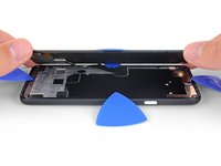
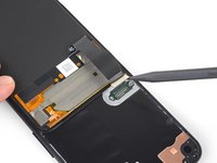
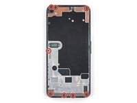
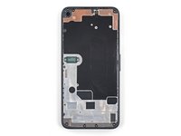
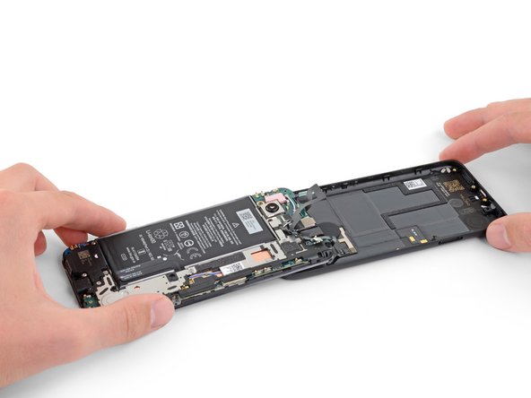
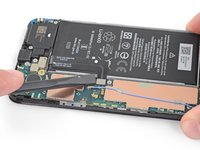
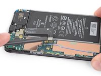
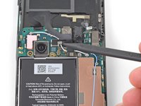
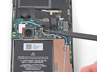
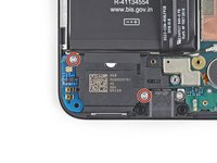
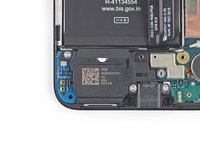
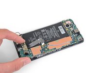
This photo shows the midframe components behind the back cover. Note the spring contacts near the edge of the midframe. As you slice with the opening pick in the next step, be sure not to insert the pick more than 2 mm to avoid damaging the spring contacts.
-
-
-
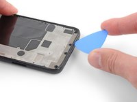
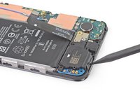
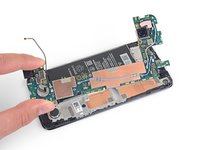
Insert an opening pick into the seam between the midframe and the back cover. Angle the pick downwards at a steep angle into the seam.
-
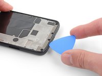
Slide the opening pick along the bottom edge of the phone to release the plastic clips securing the back cover to the midframe.
It wasn't clear to me from the picture, but don't try to pry the midframe piece up from the back cover. Pry the vertical edge of the back cover just a little out from the edge of the midframe. This releases the clip rather than fighting the clip, and the midframe will pop up from the back cover.
Be very careful at the top edge of the cover where the headphones jack is located! The plastic is very thin at the top of the opening. I was not careful, and cracked the cover near the opening. Not the end of the world, but perhaps you will be more lucky now that you know about this pitfall!
Schritt 18, Achtung ! - mit dem Plektrum muss senkrecht von der Mittelwand gegen den Rand der Rückabdeckung gehebelt werden und auch so weitergeführt werden. Wenn das Plektrum wie gezeichnet etwas unter dem Mittelrahmen geführt wird, können sehr empfindliche Kontaktfeder zerstört werden - Totalausfall. Ich habe einen Kontakt mit einer Leitung überbrücken müssen. Jeder Praktiker wird das Plektrum senkrecht ansetzen.
Dem iOpener ist der Kleber auch nicht zu lösen, ein Fön muss benutzt werden.EN : The retaining clips are pretty hard to release on the bottom. Start from the left corner underneath the Sim card tray then go all the way up and all around the phone then finish with the bottom part shown on the picture.
FR : Les clips de maintien sont durs à libérer sur le bas. Commencez par le coin gauche juste sous le tiroir Sim puis remontez et faites tout le tour du téléphone puis terminez par la partie basse indiquée sur la photo.
-
-
-
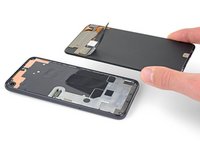
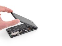
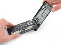
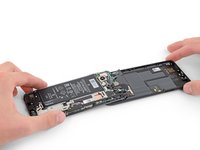
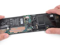
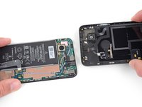
Carefully swing the back cover from the bottom of the phone over the top and around the back.
-
Lay the back cover on the work surface and lightly rest the midframe on the back cover, being careful not to put any stress on the attached ribbon cables.
I can't stress enough (no pun intended!) the need for NOT stressing these cables and connectors more than absolutely necessary! Having successfully completed the entire battery replacement and then reconnecting the fingerprint sensor connector, that cable suddenly snapped in half, probably fatiguing from too much flexing. The phone still works of course, but without a fingerprint sensor. In my opinion, this was the most crucial part of the disassembly/reassembly.
-
-
-
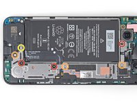
Use a T3 Torx driver to remove the seven screws securing the motherboard bracket:
-
Three 2.9 mm-long black screws
-
Three 2 mm-long screws
-
One 4.1 mm-long screw
-
-
-
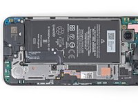
Use the tip of a spudger to unclip the motherboard bracket from the upper-right and lower-right corners of the motherboard.
on mine, the fingerprint sensor cable was lightly adherent to the bracket and I almost tore it when the bracket popped up. may want to add something about freeing this up before removing the bracket.
Similar to Erik, my fingerprint sensor cable was adhered to the bracket and mine did tear. I didn't use the fingerprint sensor, so hopefully this doesn't affect anything else with the phone. Now I know to read the comments! X_X
I had the same issues: The cable was attached to the bracket and I had to be very careful in pushing the bracket to the side and reach under it with the spudger to detach the fingerprint cable. And I also found the top clip of the bracket hard to unclip. It worked when I started with the lower one and then pushed the bracket to the side a bit. It seemed to be glued on the top corner.
My fingerprint sensor cable was also glued to the bracket, but it seems like a sturdy cable so was not easily damaged
Ok this was really bad for me I did not understand how the clip was oriented and tried to pull it up lightly first and then strongly, it finally came off but I bent and broke the bridge just a bit, and most importantly the RFID or fingerprint sensor cable (the circle in the back). I don't use it and nothing more was harmed managed to put everything back in place but
Beware of the clips, you have to pull them TOWARDS you, then the bridge will pop-up, don't apply strength upwards before unclicking the 2 clicks towards you (horizontal plane)This is also what worked for me. I put the lid over the rest of the board, to protect the cable (after reading the comments) and used the tweezers to carefully pull the piece towards me and then lifted it up.
this is the most frustrating step in the entire guide. i used tweezers and pushed to the left of the upper bracket to free it. no upward force is required to free it. be careful
My spudger tip was bending trying to release the bracket - I used a 1mm flathead screwdriver instead, from just below the clip, and it popped up beautifully and with no force. Cables all intact!
The fingerprint sensor cable is the smaller one and it is indeed glued to the top of the motherboard bracket. First free it with the spudger before proceeding.
Always remove the bottom-left clip first as it reduces force.
I should also note that if you hate re-attaching ribbon cables like me and want to ensure the fingerprint sensor cable won't break then it is enough to only remove the bottom-left clip, gently lift the motherboard up and to the side and use the spudger to detach the battery cable. Steps 26 and 27 can be skipped and you simply keep the back frame attached. Do Steps 28-30 before unscrewing the mid frame for easier pulling on the battery adhesives. After the battery cable is free flip the back cover again, then drop the IPA in if needed to free the battery fully.
Just be careful with pressure. After installing the new battery lift the motherboard up again and re-attach the battery cable which isn't too bad. Then clip the motherboard back into place and proceed.
Fingerprint sensor cable saved!
Free the smaller cable first. If you do this there is no risk of breaking fingerprint sensor. You will know what to do when you see it. After freeing cable you can pull the metal stuff upwards safely with any force you want. The risk is gone
Like for many others, this step didn't work well for me. The instructions should really clearly state that you need to pull towards the outside to unclip the motherboard bracket.This is what the clip on the upper right of the motherboard bracket looks like in profile. Also, my spudger tip bent and almost broke. I had to use a small screwdriver to be able to apply enough force to unclip.
Inordinately complicated and a severe design fault. Thank God they did not design a car battery.
Thanks to all the comments! Unglued my fingerprint cable before following @rkj tip on pulling the bracket towards you and it popped out like a charm. ifixit should highlight the comments or something if they have a lot of interaction going like this cause this probably saved me from a headache from an other wise smooth replacement.
EN : I strongly advise you to do steps 26 and 27 before doing this step. Don't touch the retaining clip shown on the picture, leave it for the end. Gently lift the bracket from the opposite side and release the 2 ribbon cables. My fingerprint sensor cable was also glued to motherboard bracket so be careful. Then remove the back cover. You can now easily remove the motherboard bracket.
FR : Je recommande fortement de faire les étapes 26 et 27 avant cette étape. Ne touchez pas le clip de maintien montré en photo, gardez-le pour la fin. Soulevez délicatement le cache côté opposé et libérez les 2 nappes. La nappe de mon lecteur d'empreintes était également collée au cache de la carte mère donc faites attention. Puis retirez la coque arrière. Maintenant vous pouvez facilement retirer le cache de la carte mère.
-
-
-
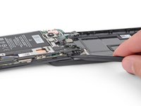
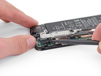
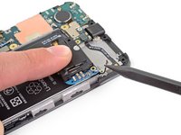
Use the flat end of a spudger to pry up and disconnect the battery cable.
-
-
-
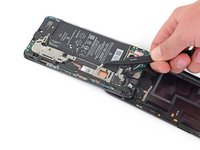
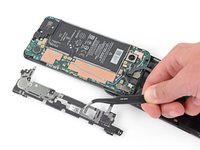
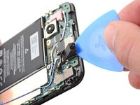
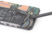
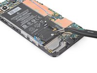
Use the tip of a spudger to disconnect the two flex cables connecting the fingerprint sensor and buttons to the motherboard.
-
-
-
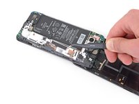
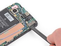
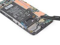
Use the tip of a spudger to disconnect the headphone jack cable from the motherboard.
-
-
-
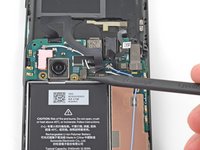
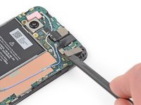
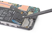
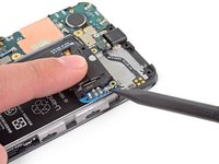
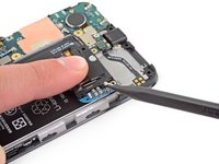
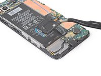
Insert an opening pick under the headphone jack and twist to release it from the adhesive securing it to the midframe.
-
Remove the headphone jack.
There shouldn't be a need to remove the headphone jack to get to the charging port since you have already disconnected it from the board.
I did not remove the microphone jack as you suggested and it was fine, thanks!
IFuxedIt -
I also tried skipping the step but then trapped the cable under the motherboard on reassembly. I would say for that reason that it's safer to fully remove.
I found it very hard to get the opening pick in and pry out the headphone jack. I eventually resorted to applying the heating pack that you also use at the beginning to get the screen out. Then gently push the pick upward inside the hole of the headphone jack to lift its edge up slightly to get the pick eventually in underneath.
-
-
-
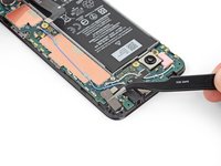
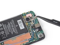
Pry up with the flat end of a spudger to disconnect the front-facing camera from the motherboard.
-
-
-
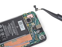
Use a T3 Torx driver to remove the two 4.1 mm screws securing the loudspeaker assembly.
-
-
-
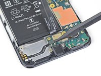
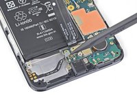
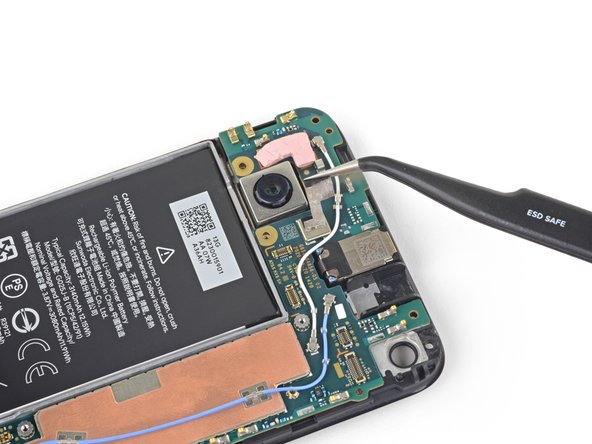
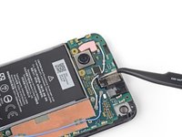
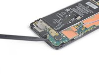
Use the tip of a spudger to disconnect the antenna flex cable from the loudspeaker assembly.
Reversing this step was the most difficult part of the repair from me. The small board attached to the speaker get getting loose, especially when trying to reattach the antenna. The antenna cable was continuously in the way when trying to reposition the speaker to its original position. After a lot of patience the repair was completed without any issues. The new usb-c port is great!
Seconding that this was fiddly on reassembly! I found the antenna attachment easier to do once I got the wire part back into its tiny guide clips on the board. This also helped me position it for putting the loudspeaker back into place - it needs to run along what will be the top of the speaker unit once it sits down again. The little circuit board does come loose easily but it will snap back into place with gentle pressure so don't stress too much if it comes free on reassembly!
-
-
-
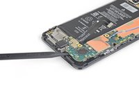
Carefully peel the loudspeaker assembly up off of the tape underneath it.
-
Remove the loudspeaker assembly.
when reassembling: I found it easier to lay the loudspeaker in its ultimate position, then smooth the tape back down onto it.
-
-
-
Use the tip of a spudger to disconnect the loudspeaker cable from the motherboard.
Be careful on this step. I ended up popping out part of the clip housing (I may be able to repair once I look at it with a magnifying glass). Maybe the flat side of the spudger would be better.
-
-
-
Use a T3 Torx driver to remove the three screws securing the motherboard:
-
Two 2.9 mm-long black screws
-
One 2.1 mm-long screw
-
-
-
Use the corner of an opening pick to peel up the tape covering the earpiece speaker.
-
-
Outil utilisé dans cette étape :Tweezers$4.99
-
Use a pair of tweezers to completely remove the tape covering the earpiece speaker.
-
-
-
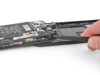
Insert the tip of a spudger underneath the bottom edge of the motherboard and pry it up enough to grip it with your fingers.
when reversing this step, be sure not to trap any of the cables below it - especially the loudspeaker cable, which has very little available flex to get out of the way.
-


Compare your new replacement part to the original part—you may need to transfer remaining components or remove adhesive backings from the new part before installing.
To reassemble your device, follow the above steps in reverse order.
Take your e-waste to an R2 or e-Stewards certified recycler.
Repair didn’t go as planned? Try some basic troubleshooting, or ask our Answers community for help.
Annulation : je n'ai pas terminé ce tutoriel.
9 autres ont terminé cette réparation.

6 commentaires
Longshot here… I dropped my phone and it appears to be dead, although no physical signs of damage. Right after it happened, I could see an image on the screen but it was frozen, so I pressed the power button and the screen turned off, and then I wasn’t able to turn it back on from then on. There are no signs of life at all… no lights, no vibrations, no sounds. If I plug it into my computer, nothing happens. So totally dead. I already opened it up and checked for any obvious damage to internal components or loose cables. Didn’t find any smoking guns, so I just tried disconnecting and re-connecting all the ribbon cables. Still no success. I’m wondering if you have any thoughts on whether a battery or motherboard replacement might bring my phone back to life, and if so, if you have any thoughts on one or the other. My initial thought is that’s it more likely that something on the motherboard got damaged from a physical drop vs. the battery, but any other input you could offer would be great.
That’s a tough one Sally… I can’t guarantee replacing any certain component will fix your phone given the information. Disconnecting and reconnecting the cables was a good idea. No signs of life at all suggests to me it’s likely the battery or motherboard, like you said.
If it’s still under warranty see if Google will replace it, they replaced my pixel 3 twice when it bricked for no apparent reason. If it’s not then I think the best course of action would be to meticulously search for the damage starting with the motherboard. Use a magnifying glass. Even if a single tiny transistor popped off that would be enough to brick it. If you can’t find anything, you’ll have to take a chance replacing one part at a time until you get it working again.
Good luck!
Hey there, probably no fix to this, but I went swimming in a salt water pool with my 4a on accident and the repair store said the motherboard was fried and unrepairable. Is there any chance that I can still get data off the phone?
Unfortunately, even if you disassemble your phone clean it in an ultrasonic bath, then replace the battery, you’d still have to be very lucky for it to power back on with data intact.
I'm using Pixel 4a but my Sim side is not working
Boakye John Owusu - Réponse
The pliers (came with the kit) end worked for this step
Gabriel Basilio Brito - Réponse
For some odd reason, I was unable to put the SIM tray back after a successful repair!? It stands out by half a milimeter now, it works, but it's like a button in terms of how much it overlaps now. So, be careful, I guess, although I am unsure what is causing this.
Roman - Réponse
Good . It's good idea for this instructions
Joramu Thomas - Réponse