Cette version peut contenir des modifications incorrectes. Passez au dernier aperçu vérifié.
Ce dont vous avez besoin
-
Cette étape n’est pas traduite. Aidez à la traduire
-
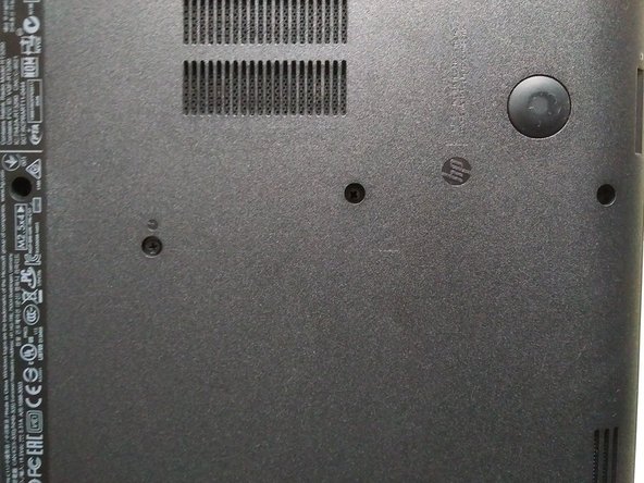
Remove the two indicated screws using a #1 Phillips driver.
-
-
Cette étape n’est pas traduite. Aidez à la traduire
-
Use a #1 Philips driver to remove the disc drive's screw.
-
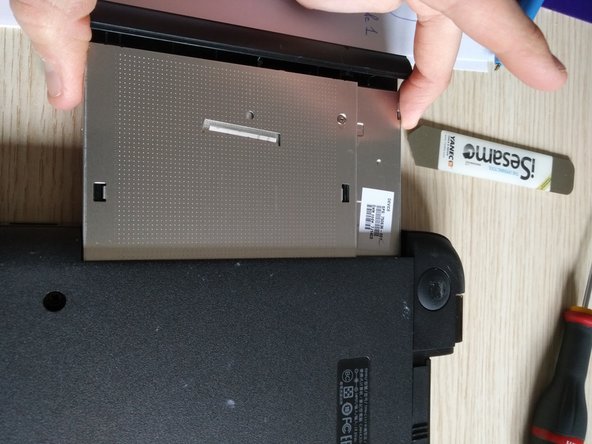
Using a spudger, gently pry the drive out of the housing.
-
-
Cette étape n’est pas traduite. Aidez à la traduire
-
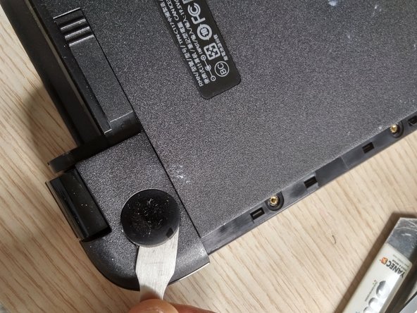
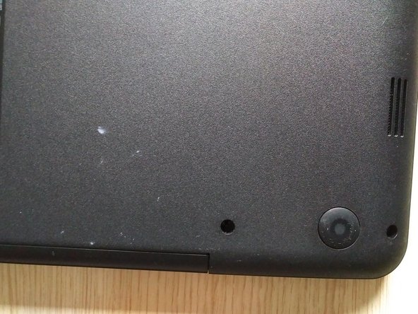
Remove the rubber rests on the rear of the device, which are close to the battery.
-
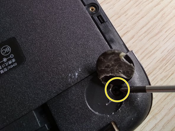
Remove the hidden screws placed under the rests using a #1 Philips driver.
-
-
Cette étape n’est pas traduite. Aidez à la traduire
-
Remove the remaining screws on the bottom of the device.
-
-
Cette étape n’est pas traduite. Aidez à la traduire
-
Remove the two little screws at the DVD entrance.
-
-
Cette étape n’est pas traduite. Aidez à la traduire
-
Turn the laptop around.
-
Open up the laptop (to remove the keyboard).
-
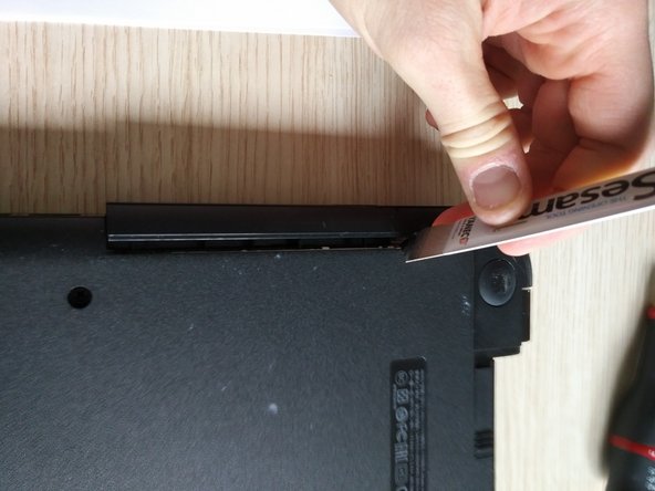
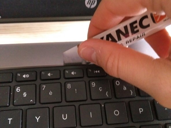
Use a spudger or iSesamo to remove the keyboard.
-
Slide the iSesamo around the upper side of the keyboard as shown in the pictures (you will hear clicks).
-
-
-
Cette étape n’est pas traduite. Aidez à la traduire
-
When it becomes loose, gently slide the keyboard to the left as shown in the third picture.
-
-
Cette étape n’est pas traduite. Aidez à la traduire
-
Gently lift the keyboard up.
-
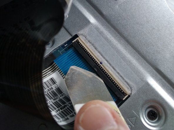
Spot the thin ribbon cable attached to the connector (the connector has a plastic lid).
-
Carefully open the lid with a spudger and slide the ribbon cable out of the connector.
-
Close the lid after removing the cable so that the cable cannot fall out.
-
-
Cette étape n’est pas traduite. Aidez à la traduire
-
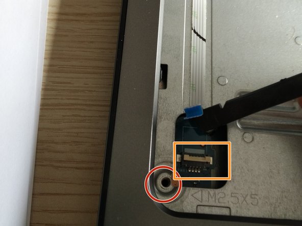
Remove the screw circled in the second picture.
-
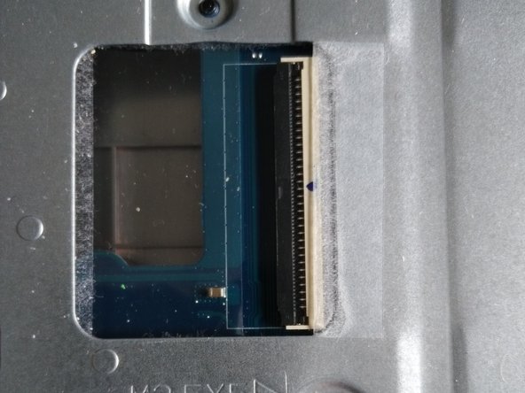
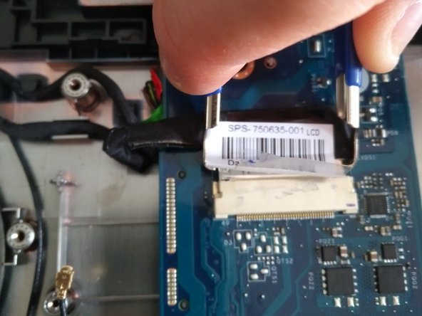
Remove the tape over the cable and the connector.
-
Remove the white ribbon cable from the connector.
-
Open up the lid with a spudger, and gently remove the ribbon cable.
-
-
Cette étape n’est pas traduite. Aidez à la traduire
-
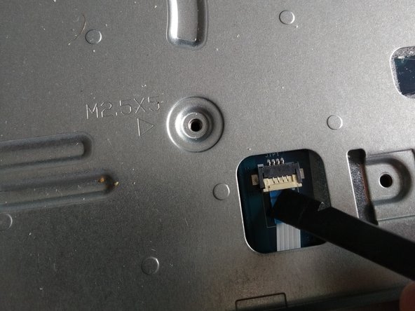
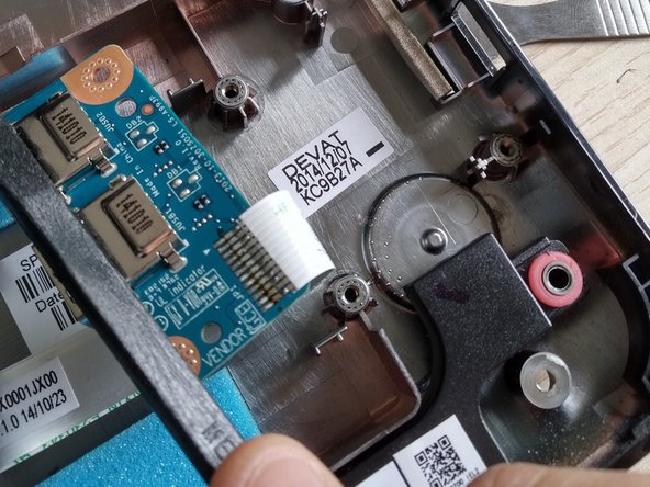
Remove the circled screw.
-
Remove the ribbon cable from the connector.
-
-
Cette étape n’est pas traduite. Aidez à la traduire
-
Remove the screw on the upper side of the laptop.
-
-
Cette étape n’est pas traduite. Aidez à la traduire
-
Remove the last screw (unfortunately, I do not have a picture of this, but you will see it on your laptop).
-
-
Cette étape n’est pas traduite. Aidez à la traduire
-
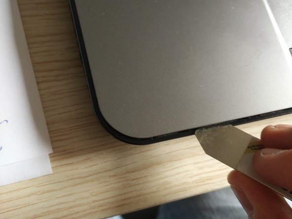
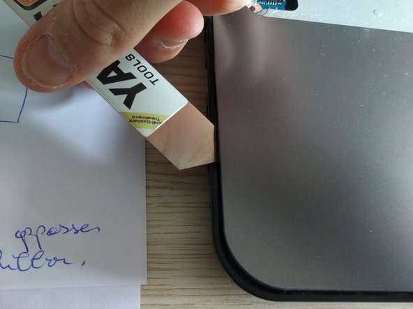
Slide your iSesamo around the case as shown in picture 1 and 2, and go around the entire laptop.
-
Lift the upper plate to reveal the motherboard.
-
-
Cette étape n’est pas traduite. Aidez à la traduire
-
Remove the two screws holding the main board to the plate (see pictures two and three).
-
-
Cette étape n’est pas traduite. Aidez à la traduire
-
Use an IC extractor to remove the audio connector from the socket.
-
-
Cette étape n’est pas traduite. Aidez à la traduire
-
Remove the two screws holding the HDD.
-
Slide out the HDD.
-
-
Cette étape n’est pas traduite. Aidez à la traduire
-
Use a spudger to loosen the cable from the bottom plate.
-
-
Cette étape n’est pas traduite. Aidez à la traduire
-
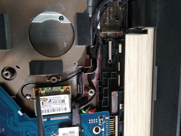
Remove the golden antenna cable from the socket. Be very careful, and use a spudger.
-
Remove the screw.
-
The WiFi module will jump up when the screw is removed. Slide the WiFi module out.
-
To install the new Wifi module, slide the new WiFi module in, push it down, and drive the screw back in.
-
Reattach the antenna.
-
-
Cette étape n’est pas traduite. Aidez à la traduire
-
If the DC jack is damaged or broken in your laptop, remove the hinge instead (this is holding the DC power jack in place).
-


Annulation : je n'ai pas terminé ce tutoriel.
10 autres ont terminé cette réparation.
