Cette version peut contenir des modifications incorrectes. Passez au dernier aperçu vérifié.
Ce dont vous avez besoin
-
-
Retirez les dix vis suivantes par lesquelles le boîtier inférieur est fixé au boîtier supérieur :
-
Sept vis Phillips 3 mm.
-
Trois vis Phillips 13,5 mm.
-
-
J'achèteOutil utilisé dans cette étape :P6 Pentalobe Screwdriver 2009 15" MacBook Pro Battery$5.49
-
Trois vis Pentalobe fixent la batterie au boîtier supérieur. Vous pouvez les dévisser avec ce tournevis spécial.
-
-
Cette étape n’est pas traduite. Aidez à la traduire
-
Use the flat end of a spudger to pry the fan cable connector up off its socket on the logic board.
-
-
Cette étape n’est pas traduite. Aidez à la traduire
-
Remove the three identical T6 Torx screws securing the fan to the upper case.
-
-
Cette étape n’est pas traduite. Aidez à la traduire
-
Hold the end of the cable retainer down with one finger while you use the tip of a spudger to slightly lift the other end and rotate it away from the camera cable connector.
-
-
Cette étape n’est pas traduite. Aidez à la traduire
-
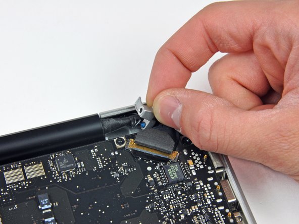
Disconnect the camera cable by pulling the male end straight away from its socket.
-
-
Cette étape n’est pas traduite. Aidez à la traduire
-
Use the flat end of a spudger to pry the optical drive cable connector up off the logic board.
-
-
-
Cette étape n’est pas traduite. Aidez à la traduire
-
Using the flat end of a spudger, pry the subwoofer connector straight up off the logic board.
-
-
Cette étape n’est pas traduite. Aidez à la traduire
-
Use the flat end of a spudger to pry the hard drive/IR sensor cable connector up off the logic board.
-
-
Cette étape n’est pas traduite. Aidez à la traduire
-
Remove the two 1.5 mm Phillips screws securing the cable cover to the logic board.
-
Lift the cable cover out of the upper case.
-
-
Cette étape n’est pas traduite. Aidez à la traduire
-
Use a spudger to pry the trackpad flex ribbon cable connector up off the logic board.
-
-
Cette étape n’est pas traduite. Aidez à la traduire
-
Using the tip of a spudger, flip up the keyboard ribbon cable retaining flap.
-
Pull the keyboard ribbon cable straight out of its socket.
-
-
Cette étape n’est pas traduite. Aidez à la traduire
-
Use a spudger to pry the battery indicator ribbon cable connector up off the logic board.
-
-
Cette étape n’est pas traduite. Aidez à la traduire
-
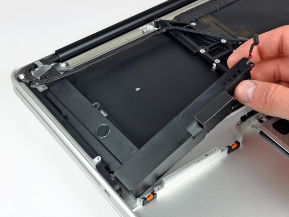
Remove the single 7 mm Phillips screw securing the display data cable retainer to the upper case.
-
Remove the display data cable retainer from the upper case.
-
-
Cette étape n’est pas traduite. Aidez à la traduire
-
Grab the plastic pull tab secured to the display data cable lock and rotate it toward the DC-in side of the computer.
-
Pull the display data cable connector straight away from its socket.
-
-
Cette étape n’est pas traduite. Aidez à la traduire
-
Using the tip of a spudger, flip up the keyboard backlight ribbon cable retaining flap.
-
Pull the keyboard backlight ribbon cable straight out of its socket.
-
-
Cette étape n’est pas traduite. Aidez à la traduire
-
Remove the following screws:
-
Eight 3.5 mm T6 Torx screws securing the logic board to the upper case.
-
Two T6 Torx screws securing the DC-In board to the upper case.
-
-
Cette étape n’est pas traduite. Aidez à la traduire
-
Carefully lift the logic board assembly from the left side and work it out of the upper case, minding the port side that may get caught during removal.
-
-
Cette étape n’est pas traduite. Aidez à la traduire
-
Lift the logic board enough to gain clearance and use a spudger to pry the microphone up off the upper case.
-
Slide the logic board away from the port openings and lift the assembly out of the upper case.
-
-
Cette étape n’est pas traduite. Aidez à la traduire
-
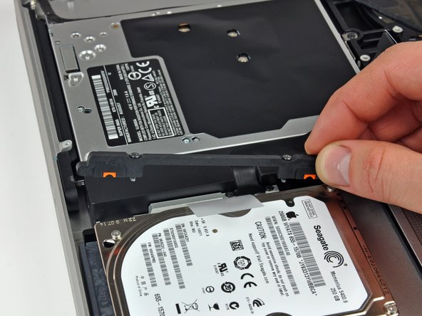
Remove the two Phillips screws securing the hard drive bracket to the upper case.
-
Remove the hard drive bracket from the upper case.
-
-
Cette étape n’est pas traduite. Aidez à la traduire
-
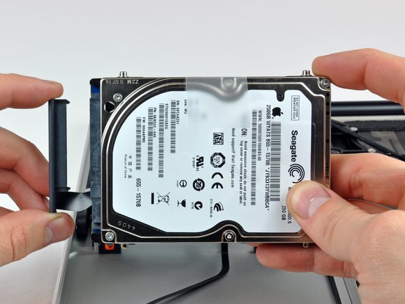
Lift the hard drive out of the upper case by its plastic pull tab, minding the cable attaching it to the computer.
-
-
Cette étape n’est pas traduite. Aidez à la traduire
-
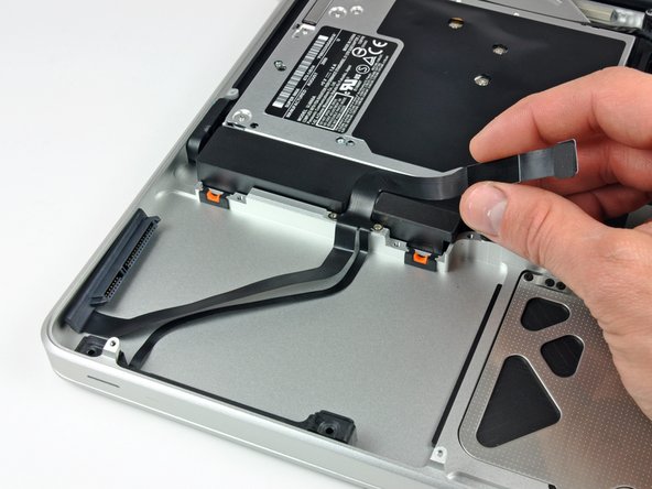
Remove the hard drive from its cable by pulling the cable connector straight away from the drive.
-
-
Cette étape n’est pas traduite. Aidez à la traduire
-
Remove the following four screws securing the hard drive and IR sensor cable to the upper case:
-
Two 1.5 mm Phillips screws.
-
Two 4 mm Phillips screws.
-
Slide the hard drive and IR sensor bracket away from the edge of the upper case.
-
Carefully peel the hard drive and IR sensor cable from the upper case.
-
Remove the hard drive/IR sensor cable from the upper case and set it aside.
-
-
Cette étape n’est pas traduite. Aidez à la traduire
-
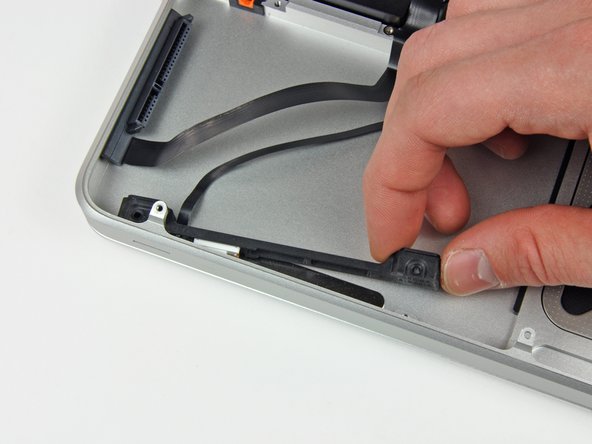
Disconnect the Bluetooth cable by pulling the male end straight away from its socket.
-
Use the flat end of a spudger to carefully pry the AirPort antenna off its socket on the AirPort card.
-
-
Cette étape n’est pas traduite. Aidez à la traduire
-
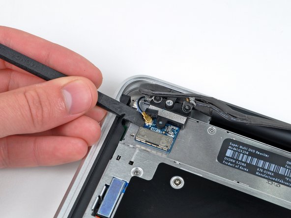
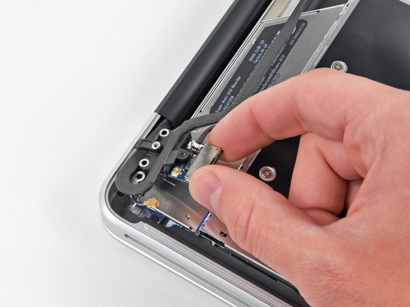
Remove the two 8 mm Phillips screws securing the Bluetooth/camera cable retainer to the upper case.
-
Lift the AirPort board/cable retainer assembly out of the upper case.
-
-
Cette étape n’est pas traduite. Aidez à la traduire
-
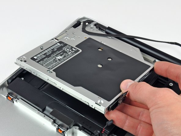
Remove three 3.5 mm Phillips screws securing the optical drive to the upper case.
-
Lift the optical drive from its left edge and pull it out of the computer.
-
-
Cette étape n’est pas traduite. Aidez à la traduire
-
Remove the following four screws securing the subwoofer and right speaker to the upper case:
-
Two 3.2 mm Phillips screws.
-
One 2.6 mm Phillips screw.
-
One 5 mm Phillips screw.
-
Lift the subwoofer and right speaker assembly out of the upper case.
-
-
Cette étape n’est pas traduite. Aidez à la traduire
-
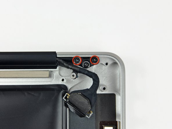
Remove two outer 6 mm Torx screws securing each side of the display to the upper case (4 screws total).
-
-
Cette étape n’est pas traduite. Aidez à la traduire
-
Open your MacBook Pro so the display is perpendicular to the upper case.
-
Place your opened MacBook Pro on a table as pictured.
-
While holding the display and upper case together with your other hand, remove the 6 mm Torx screw from the lower display bracket.
-
-
Cette étape n’est pas traduite. Aidez à la traduire
-
Remove the last remaining 6 mm Torx screw securing the display to the upper case.
-
-
Cette étape n’est pas traduite. Aidez à la traduire
-
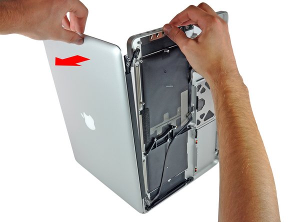
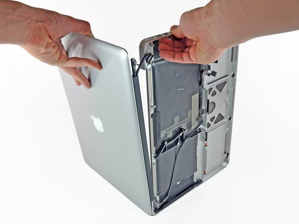
Grab the upper case with your right hand and rotate it slightly toward the top of the display so the upper display bracket clears the edge of the upper case.
-
Rotate the display slightly away from the upper case.
-
Lift the display away from the upper case, minding any brackets or cables that may get caught.
-


Annulation : je n'ai pas terminé ce tutoriel.
3 autres ont terminé cette réparation.
