Introduction
Cela résout le problème des disques de jeu qui ne sont pas lus correctement.
IMPORTANT: Les étapes 11 à 16 ne servent à rien ici et ne feront qu'allonger le processus. Pour vous épargner du temps et des efforts, passez directement de l'étape 10 à l'étape 17.
Ce dont vous avez besoin
-
-
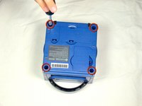
Retournez la Gamecube de manière à ce que la face inférieure soit tournée vers le haut.
-
Utilisez le tournevis Gamebit de 4,5 mm pour retirer les quatre vis.
-
-
-
Avec la face inférieure de la GameCube tournée vers le haut et les vis retirées, retirez délicatement la coque extérieure de l'unité de la moitié supérieure.
-
Déplacez la GameCube de manière à ce que l'intérieur soit orienté vers le haut.
This can also be done whilst being in the normal upright position after all 4 of the 4.5mm Gamebit screws have been removed. Pull the top of the shell directly upwards and it should slide off easily.
Less chance of snagging any wires or parts.
-
-
-
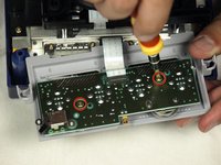
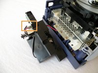
Appuyez doucement sur les clips situés de chaque côté du panneau arrière.
-
Retirez avec précaution le panneau arrière du GameCube.
A second picture clearly showing which direction to pull the back panel away from the unit would be nice.
-
-
-
Déclipsez soigneusement les ports du contrôleur à l'avant de l'unité.
well... what happens if accidentally i disconnected it?
presumably nothing major. The CMOS battery is attached to the controller ports, so the most i'd expect is that the gamecube loses it's date/time setting. As long as you reset that before jumping into animal crossing or something, you should be fine. I'm currently doing a teardown of my gamecube, and if something does prove to have gone wrong, i'll report back.
sigoshi -
okay, i finished putting it back together. gamecube works fine and surprisingly still remembers what year it is. boots into smash bros and shows memory card contents fine.
sigoshi -
-
-
-
Utilisez un tournevis Phillips #2 pour retirer les deux vis à l'arrière du port de contrôle.
-
Séparez soigneusement l'enveloppe extérieure grise du port de commande et la carte de circuit imprimé.
must do this?
That step is not needed for the laser replacement.
Love ur labeling and legends. Good on ya
Not a necessary step
-
-
-
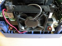
Le côté gauche de l'unité contient le ventilateur de refroidissement et son boîtier.
-
Retirez avec précaution les deux (2) vis fixant le boîtier du ventilateur de refroidissement à l'unité.
Why can't the fan wire be detached?
It can, but you might not want to
-
-
-
-
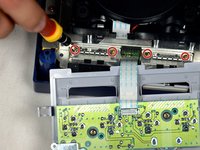
Le lecteur optique est fixé sur une plaque métallique.
-
À l'aide d'un tournevis cruciforme n° 2, dévissez les douze vis qui se trouvent autour du bord extérieur du lecteur optique.
Are these 12 screws the exact same kind like the 2 that were on the fan?
Yes! As far as I can tell anyway. Makes sense, too since opposite the fan you have five of the same holes as well.
-
-
-
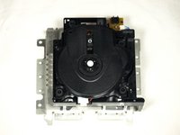
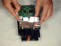
Séparez soigneusement l'ensemble lecteur optique du reste de l'unité GameCube.
-
L'ensemble lecteur optique est fixé à la carte mère en dessous par une fente; une certaine force peut être nécessaire pour libérer soigneusement l'assemblage.
-
La plaque métallique et le lecteur optique proprement dit resteront attachés.
-
-
-
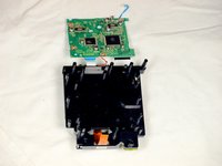
À ce stade, votre ensemble de lecteur optique doit être séparé de votre GameCube.
-
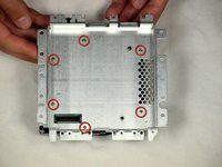
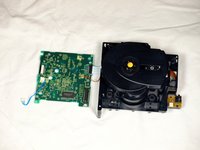
Retournez l'assemblage du lecteur optique à l'envers
-
Retirez les six vis à l'aide d'un tournevis Phillips #1.
-
Soulevez délicatement la plaque métallique et retirez-la.
If you are just doing the lens power adjustment, from this step skip straight to step 17. Steps 11-16 are unnecessary unless you are replacing the lens completely.
-
-
-
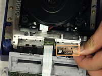
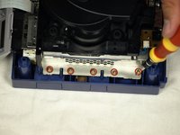
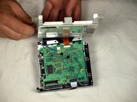
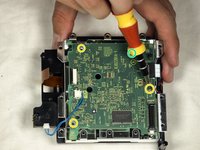
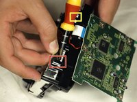
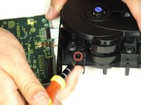
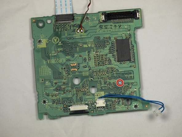
Retirez le fil bleu en tirant doucement.
-
Débranchez le câble marron. Pour ce faire, tirez doucement sur la languette noire pour l'écarter du plastique blanc. La tension sur le câble marron se relâchera, ce qui lui permettra de se détacher doucement de la languette.
-
Retirez les quatre vis Phillips #1 qui relient la carte de circuit imprimé à l'assemblage du lecteur optique.
-
La quatrième vis se trouve derrière le tournevis de la troisième photo.
A helpful addition/change to this step would be to include a photo of where/how to remove the brown ribbon cable (maybe also include this terminology in the text, instead of just “cable”). Furthermore, the yellow box to indicate the blue cable highlights everything except the part that you need to remove, which is a little confusing.
Thanks!
Ben
I cannot get the 4 little screws to go back into the board once removed. There is nothing for them to bite into - how do I get this board put back together?
I had this same issue — until I realized that the metal plate goes back on BEFORE the circuit board XD. Once you out the metal plate back on and put the circuit board on top of that, the screws should go in okay.
-
-
-
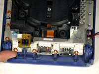
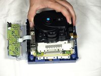
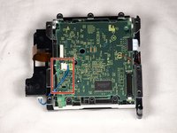
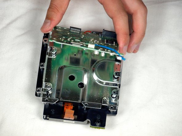
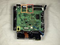
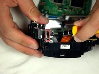
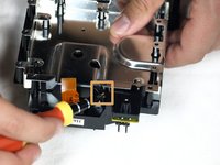
Détachez le petit clip qui maintient la planche vers le bas.
-
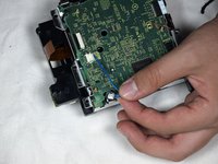
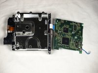
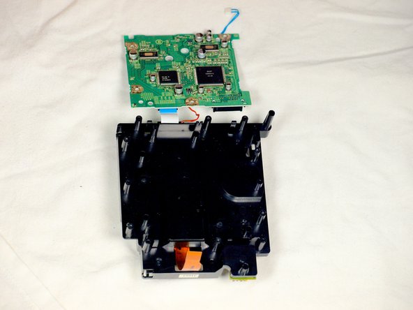
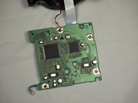
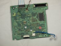
Retirez délicatement le circuit imprimé (le grand carré vert) comme indiqué sur les trois images.
-
Cable rouge
-
Câble ruban blanc
What would happen if I accidentally separated the white ribbon cable... because I watched a video of some guy going through this same process. Separated all the cables and his worked. My cube stopped reading disks recently. Laser is calibrated properly. Begins to spin then stops
Ps
Is there anyway I can save my cube
I'm just guessing here, but I think they mean there's no need to separate those cables to complete the repair—just be careful not to pull or stress them. Like you said, nothing bad will happen if you choose to disconnect a couple cables. As for what's wrong with your cube, you might want to try asking your question over in the Answers forum.
There is a small tab to the left of the red wire that you need to pull out to release the circuit board.
Why do we need further disassembly that this ? The potentiometer is already accessible at this point. Why do we need to tear down the lens from it’s slot in step 16 ?
Good question! I’m wondering the same thing.
You don’t. You can stop here if you’re doing the laser potentiometer calibration.
jweeman -
-
-
-
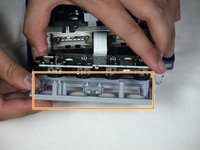
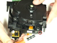
Utilisez un tournevis à tête plate pour libérer soigneusement les quatre clips en plastique qui maintiennent l'ensemble d'entraînement ensemble.
-
Utilisez avec précaution un tournevis comme levier pour dévisser et libérer le dernier clip.
Since this step uses a flathead screwdriver, it might be useful to include that in the list of required tools at the top.
-
-
-
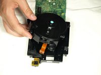
Utilisez un tournevis à tête plate pour libérer les deux clips situés sur la moitié arrière de l'ensemble d'entraînement.
-
Le clip final n'a pas besoin d'être diffusé ; la moitié supérieure de l'ensemble d'entraînement glissera loin de la moitié inférieure.
-
Terminez de retirer la moitié supérieure de l'ensemble d'entraînement de la base.
-
-
-
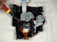
Une fois la moitié supérieure de l'ensemble d'entraînement détachée, retournez-la.
-
À l'aide d'un tournevis cruciforme, retirez avec précaution les trois dernières vis situées près des barres d'assemblage des lentilles.
-
Dévissez les trois dernières vis et retirez l'ensemble de la lentille.
what kind of screws are these on the laser lens i lost one and need to buy new ones cause i cant find the 3rd
we're replacing the laser tho
-
-
-
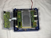
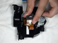
Faites pivoter l'ensemble de manière à ce que la carte mère verte soit face à vous, comme indiqué sur la première photo.
-
Retourner la carte de manière à ce qu'elle soit orientée comme indiquée sur la deuxième image.
-
À l'aide d'un tournevis Phillips #1, tournez le petit bouton très légèrement dans le sens inverse des aiguilles d'une montre - de quelques degrés à un quart de tour au maximum.
Isn't it supposed to be counter clockwise? I read somewhere that turning it clockwise weakens the laser.
Does anyone know the initial ohm potentiometer setting on Nintendo Gamecube DOL-001 (factory) on the pcb driver (RJB2281A-1 POT 0-900 OHM) THANK YOU
You don't. The author just duct taped a step to the end of the laser replacement guide and called it a day
-


Pour remonter votre appareil, suivez ces instructions dans l'ordre inverse.
Pour remonter votre appareil, suivez ces instructions dans l'ordre inverse.
Annulation : je n'ai pas terminé ce tutoriel.
29 autres ont terminé cette réparation.
Merci à ces traducteurs :
100%

Thibaud SCHNEIDER nous aide à réparer le monde ! Vous voulez contribuer ?
Commencez à traduire ›
Équipe

Cal Poly, Team 6-2, Maness Fall 2009 Membre de l'équipe Cal Poly, Team 6-2, Maness Fall 2009
CPSU-MANESS-F09S6G2
4 membres
45 tutoriels rédigés
6 commentaires
I don't understand why you have steps 11-17. In step 10, you can clearly see the board with the screw that needs adjusting. Taking apart the rest of the GameCube is utterly unnecessary. After following the guide in full, I thought, 'Why did I just dismantle all that other stuff when I didn't even NEED to?'
Once the assembly is removed from the metal covering the board, it is a simple matter to turn the screw to increase the laser strength. I did this after my initial adjustment didn't work. I ignored steps 11-17 and everything works perfectly now. My old games which simply would not load, now do. Thanks for the advice leading up to step 10 though. That part was helpful.
I wouldn't say it's a quarter of a turn, a few degrees clockwise do the trick. I tried a quarter of a turn the first time and it made the disk unit useless as it didn't recognise any gamecube disk.
Thanks for the detailed pictures! I was able to get everything taken apart, and fixed the read error I was having after a couple of readjustments.
One important note: the lens screw should be turned counter-clockwise, not clockwise. A quarter turn is also likely to be too much; better to adjust a few degrees at a time and test repeatedly until the right setting is found.
gameFAQs.com has a lens calibration guide, with notes on how to reassemble the GameCube for testing without screwing everything back together.
I also agree that steps 11-17 can be skipped, as well as step 5 to remove the controller ports.
Steps 11+ are definitely not needed and 1/4 turn is more than 200ohms, way too much. It has to be moved by a hair (almost literally), the potentiometer is extremely sensitive. And I would personally recommend some form of multimeter, as to not go turning that screw blindly.
Great guide, this fixed my problem. Would like to be clarified if you need to follow steps 11-17 make the power adjustment.
Hell yes dude, thank you! The console I got from my grandma with SA2B as a preteen finally stopped reading discs completely yesterday after having trouble on and off for years, I was afraid I'd have to replace the entire drive assembly but adjusting the lens power worked!
Also, to complete step 6, the fan is a little tricky to remove, at least on a DOL-001 US console. You have to sort of rotate the fan assembly outward clockwise, by pulling the front of the fan out to the left a bit, so the plastic can clear the drive assembly.