Il est possible que cette traduction ne reflète pas les dernières mises à jour du tutoriel source. Aidez à mettre à jour la traduction ou bien consultez le tutoriel source.
Introduction
Remplacer le boîtier supérieur nécessite d'enlever d'abord presque tous les composants de votre MacBook.
Ce dont vous avez besoin
-
-
Retirez les huit vis Phillips 4 mm par lesquelles le boîtier inférieur est fixé au MacBook.
-
-
-
Soulevez légèrement le boîtier arrière au niveau de la fente.
-
Continuez à faire courir vos doigts entre les boîtiers inférieur et supérieur jusqu'à ce que le boîtier supérieur se dégage des clips de fixation.
Do the retaining clips have to be re-engaged when replacing the lower case?
Answering my own question, the clips re-engage when the lower case is correctly positioned. You can help them by gently pressing the lower case with your thumbs midway along the two short sides. When everything is correctly aligned the eight screw holes line up.
Rather than running your fingernail down the sides to free up the retaining clips, I found that using an old credit card, inserted about 1/4”, to run along the left and right side popped those end retaining clips right off with no problem. You may need to twist the card slightly when in the middle area to help pop those off.
-
-
-
Avec l'extrémité plate d'une spatule (spudger), soulevez le connecteur de la batterie de sa prise sur la carte mère.
you do not need to remove the battery when replacing the hard drive or ram
Be careful of the corner of the battery cable connector when trying to pry it off with the spudge. I knocked the corner of mine. No operational impact but was not very pleasing!
Not necessary, but a good idea, so as to avoid any spurious charges going through the boards...
@Svenaustx - What could happen if not removing this battery? Worst case? Not a geek on this but did change RAM on my Macbook Pro "15. Can't remember disconneting the battery back then. Shouldn't it be sufficient shutting the Mac off and ensure it has been used for an hour or so before replacing RAM?
-
-
-
Retirez les vis suivantes de la grille d'aération arrière, du côté du lecteur optique :
-
Deux vis Torx T8 10 mm
-
Deux vis Phillips 5 mm
I have a problem with the two middle screws
same here...
-
-
-
Retirez les vis suivantes de la grille d'aération arrière, du côté du port :
-
Deux vis Torx T8 10 mm
-
Deux vis Phillips 5 mm
-
-
-
Sortez avec précaution la grille d'aération arrière du boîtier supérieur.
you can actually stop disassembling now and try to replace it now. after removing two t6 screws it came off pretty easily
Good tip, thanks! I skipped ahead to step 17 and had no problem getting the magsafe board out from under the logic board and the new one installed. Saves a lot of work disconnecting connectors indicated as Fragile!
matt15 -
Thank You! Saved me an hour or so of work and a lot of stress!
I also did Step 6, then skipped to Step 17 & 18. Once I had the display data cable off, I could remove the 2 T6 Torx screws holding the MagSafe board on and remove it. You can reach under the logic board with the point of the spudger to work the cable out of the socket. Note how you maneuver the board out of the tight space so you can maneuver it back in. When you put the new MagSafe board in, plug in the cable first. If you bend the wires so the plug approaches the socket at the appropriate angle, you can nudge it in with the pointed end of the spudger.
Thanks a lot for this hint! You saved my macbook, when I failed to unscrew the fan because of one completely destroyed screw. Thanks to your comment I skipped steps 7-16 and went straight to replacing the magsafe board without problems. The spudger and some 3D imagination and done,
-
-
-
Avec l'extrémité plate d'une spatule (spudger), faites levier pour retirer la nappe AirPort/Bluetooth de la carte mère.
The steps from 7 up to 16, and then 19 and 20 are not necessary. It looks like Apple intentionally designed the shape in the corner around the magsafe connector, so that it can be replaced without disconnecting and unmounting the main board. Also, the placement of the two screws mounting the magsafe board confirms that - they are easily available. This is true at least for the 2009 model, which I've successfully repaired.
So you can skip the risky steps of disconnecting of all the main board connectors and go straight to unscrewing the magsafe connector. Then, having the spudger and some 3D imagination, you can remove the magsafe board with some 3D rotations. Same for mounting the new magsafe.
I've found out that crucial simplification only because I failed to unscrew the fan (broken a screw completely, while following this guide step by step). Then I found a comment from user grze under step 6, which saved my macbook by confirming, that 7 to 16 can be skipped.
-
-
-
Avec la pointe d'une spatule (spudger), soulevez le connecteur du ventilateur vers le haut pour le débrancher de sa prise sur la carte mère.
Since this kind of connector and very fragile and easy to damage even with a spudger I use a needle that I insert in the front side of the connector, between the connector and the socket and only apply a little pressure while lifting up the needle. The connector will then pop up from one side. Repeat the procedure for the other side. With this method it's impossible to damage the connector. I adopted this method after ruining two or three connectors using the spudger.
Hi, how do you fix the axial which connects the fan with logic board..it's broken! Thanks in advance..
HELP! Both the connector AND socket detached from the logic board! Is it possible (barring micro-surgery) to reattach the socket to the logic board?
same problem here...any ideas? Did you fix it again, John?
Ben Kn -
I disconnected the connector and socket from the logic board because I wasn't being careful and wasn't using a spudger tool as was recommended. Luckily, a friend of mine that's handy with a soldering gun was able to individually solder each wire from the cooling fan's wire assembly back onto the soldering points on the logic board. It's really intricate, tricky, and risky...but at that point, what choice do you have? I verify it's possible to fix and my cooling fan is now running perfectly fine.
Hi my name is Lynn I made a mistake on the logic board trying to detach fan from laptop
A1342 and the whole thing came off so I was wondering do
I solder it back on or how can I fix it thank you and be Blessed
-
-
-
Soulevez soigneusement le connecteur fragile du haut-parleur arrière de la carte mère. Les petits connecteurs des haut-parleurs droite/gauche se cassent très facilement.
While these connectors are very delicate, a new upper body case will have new connectors already installed. I slightly broke two connectors while removing them.
Also, the connectors have a notch underneath (on the logic board) for the corner of the spudger to fit into. The hard part is that you cannot see the notches until the connectors are removed.
Hi. Long time ago, I know but.... How did you fix them?
I snapped mine off, can it be soldered back on?
Simon G -
I used pointed tip of one side of the tweezers from the ifixit Home Tech Toolkit. I found this thinner pointed tip better than a spudger for hitting that notch in the socket underneath the connectors. Since this is a metal tool, I pried very gently and I was working on a MacBook with the battery taken out entirely (early on as suggested in the video) and was also using an Anti-Static wrist strap. I found the spudger broke one of the connectors because it's relatively thick plastic, and put too much pressure under the cables before the tip could reach the plastic block of the connector. The pressure under the cable popped the wire contact right through the top of the plastic block connector. (it was OK this connector broke since I didn't need to reuse it--my replacement keyboard/upper case came with its own cables.)
Because the tips of the tweezers are angled, I felt I had better control of the torque I was applying than if I used a jeweler's flathead screwdriver.
Totally agree with the needle solution prying up from the side of the connector. A dentist tool is perfect!
(yes, in 2021 i’m fixing a 2009 macbook! :P)
-
-
-
Avec une spatule, faites levier pour retirer le connecteur du haut-parleur droit et le connecteur du LED veille de la carte mère.
-
-
-
Avec votre ongle, ouvrez le clapet de retenue de la prise ZIF de la nappe du clavier.
-
Avec la pointe d'une spatule, faites glisser la nappe du clavier hors de sa prise.
When reassembling make sure this cable is really deep in it's socket. (Use some force with the spudger wedging it in between the cable and battery). If you don't, you won't be able to power up the board. I had 2 logicboards that I thought were dead, but it turned out the cable was not inserted enough. Jump starting them with the jump pads did nothing (with or without cable connected), but connecting the cable properly made the board come alive. Really check this!!
You sir, just saved my day! Switching boards between two mac and I thought I broke the two at once... This should be documented on the manual!!
Thanks for your help!!! I thought I did the replacement wrong. Greetings from Peru.
This was hugely helpful! The cable requires much more force than expected.
'This should be added to the guide:
There really should be a comment in the steps regarding tips on how to put the ribbon back in. The tape did the trick and I am back up and running.
The two silver squares above the left corner of the Keyboard and to the right of the Trackpad cable ribbon are the jump pads to power on the MacBook if your power button may not be working.
Nope big job to replace it. Use Kapton tape to hold it in place. https://www.amazon.com/Retermit-Resistan...
-
-
-
-
Avec une spatule, soulevez le connecteur du haut-parleur gauche et le connecteur du microphone pour les débrancher de la carte mère.
Note: the 2009 and 2010 model differ here. On one the 3 point connector is left and 2 point is right, on the other one the 3 point connector is right and 2 point is left.
I found this while installing several logicboards for A1342.
@Peterdk, are the connectors exchangeable?
I mean, would putting the 3 pin on the 3 pin, and the 2 pin on the 2 pin, regardless of the position (left or right) be ok?
Have you successfully used a 2010 logic board on a 2009 case?
how do you reconnect these?
hi! i know iʻm 6 years late, and you probably figured it out already, but for the rest of us newbies , line the plug over the socket and gently press down. the correct orientation of the plug is the side with the tiny slots in them faces the logic board, aligning with the contacts in the socket. it may help to press the side farthest from the ribbon cable first.
Kahana -
-
-
-
Saisissez la languette en plastique fixée au dispositif de verrouillage du câble de données de l'écran et pivotez-la vers le côté DC-In (prise d'alimentation) de l'ordinateur.
If the video data cable has been disconnected before, the adhesive on the might not hold. Be extra cautious in disconnecting this. An illuminated magnifier would be a good help on this step as it is very delicate. This was where I feared I would fail. Was very relieved in getting through this step...
I wasn't careful enough here, and didn't realize that the silver metal piece around the connector is actually a locking clip. No wonder disconnecting the cable required more than a gentle pull. The clip popped out of the cable-side connector in the process, and was bent; fortunately I was able to very carefully bend the clip out just enough to get it re-seated in the connector; there are tiny slots on the sides of the connector that the clip fits into.
-
-
-
Dévissez les six vis Torx T6 de 4,1 à 4,4 mm fixant la carte mère au boîtier supérieur.
-
Dévissez les deux vis Torx T6 de 4,1 à 4,4 mm fixant la carte de raccordement MagSafe au boîtier supérieur.
-
Sur quelques modèles, vous pouvez trouver des vis T7. Veillez alors à ne pas abîmer la tête de vis avec un embout trop petit.
-
-
-
Soulevez le côté de la carte mère opposé aux ports hors du boîtier supérieur.
-
Faites pivoter la carte mère hors du boîtier supérieur jusqu'à ce que les ports s'écartent du bord moulé dans le boîtier supérieur.
-
Éloignez la carte mère et la carte de raccordement MagSafe du bord du boîtier supérieur, comme si elles étaient d'une pièce.
(When re-installing) Before screwing down the logic board, go around the edge and make sure no cables are caught underneath, remember there are 11 of them, 12 if the battery is present at this point.
I reassembled the macbook A1342 using this guide and everything is perfect, except that if I shut down the computer and power it up after 1hour or so, I have to press the power button a few times before it starts. What could I have gone wrong? I checked the magsafe connector and it seems to be firmly seated. :(
-
-
-
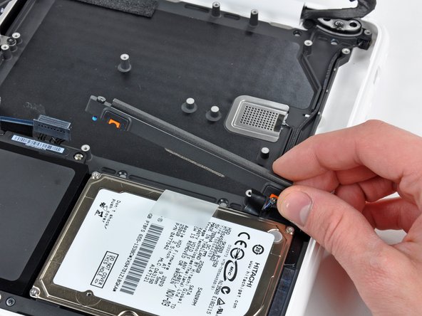
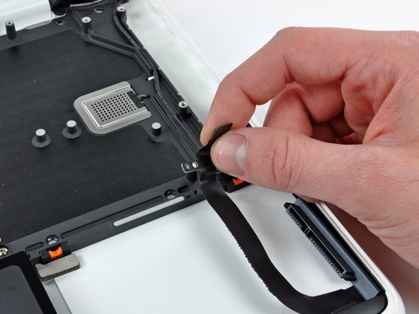
Dévissez les deux vis cruciformes Phillips attachant la fixation du disque dur au boîtier supérieur.
-
Ôtez la fixation du disque dur du boîtier supérieur.
-
-
-
Dévissez les trois vis cruciformes fixant la batterie près du bord du boîtier supérieur.
When reinstalling, I leave this step till last. It'll help you get that frackin keyboard ribbon inserted.
-
-
-
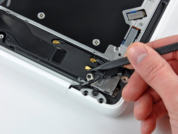
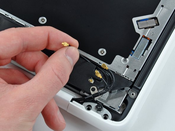
Avec la pointe d'une spatule, soulevez les connecteurs des antennes AirPort/Bluetooth (trois au total) de la carte AirPort/Bluetooth.
-
Si nécessaire, enlevez le long câble d'antenne de sa fente dans le boîtier du haut-parleur arrière.
To save some time and frustration, leave the antennae connected, just take off the 3 screws holding the speaker down and lift it out of the way. You will remove everything with the screen.
-
-
-
Dévissez l'unique vis cruciforme de 2,2 mm insérée horizontalement dans le côté du lecteur optique.
I couldn’t access this screw with the screwdriver I had (socket head was too big). But I didn’t need to remove this screw anyway. Just leave the speaker assembly (step 33) attached to the optical drive.
-
-
-
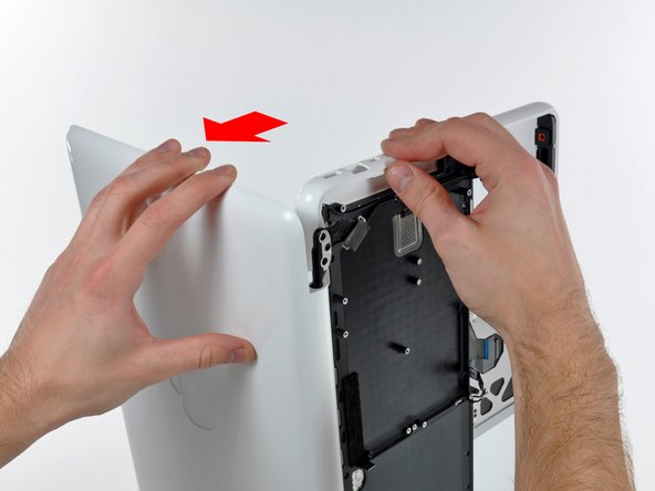
Ouvrez votre MacBook de sorte que l'écran est perpendiculaire au boîtier supérieur.
-
Posez votre MacBook sur une table comme sur la photo.
-
Pendant que vous maintenez ensemble l'écran et le boîtier supérieur avec votre main gauche, dévissez l'unique vis Torx T8 restante de la fixation inférieure de l'écran.
-
Avant de resserrer les vis Torx T8, fermez l'écran et ajustez-le afin que les bords arrières du boîtier supérieur et de l'écran soient alignés et que les interstices aux bouts de la charnière correspondent.
-
-
-
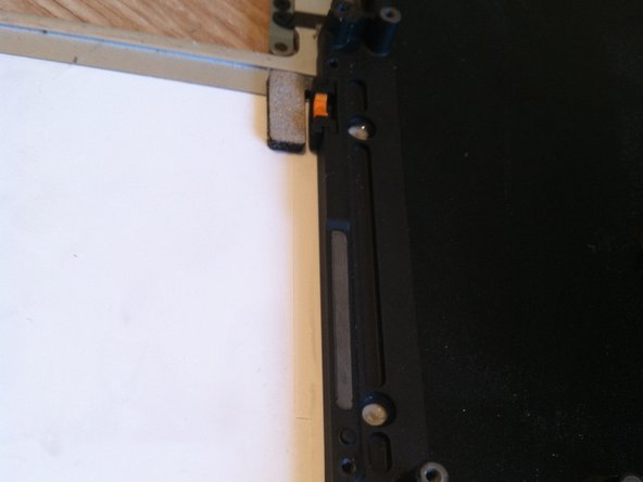
Il y a quatre inserts en caoutchouc orange et noir aux endroits où le disque dur était fixé, d'un côté des cercles complets et de l'autre des demi-cercles. (Les autres demi-cercles se trouvent sur la fixation du disque dur, qui a déjà été retirée.)
-
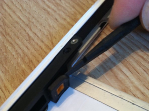
Il se peut que le nouveau boîtier supérieur n'ait pas ces inserts. Assurez-vous de les enlever de l'ancien boîtier et de les réinsérer dans le nouveau boîtier.
-
Il est facile de retirer les inserts avec une spatule ou un tournevis plat. Ils ne sont pas collés mais maintenus en place par une extrémité entaillée.
-


Pour remonter votre ordinateur, suivez les instructions dans l'ordre inverse.
Pour remonter votre ordinateur, suivez les instructions dans l'ordre inverse.
Annulation : je n'ai pas terminé ce tutoriel.
12 autres ont terminé cette réparation.
Merci à ces traducteurs :
96%


Ces traducteurs nous aident réparer le monde ! Vous voulez contribuer ?
Commencez à traduire ›

According to this page http://support.apple.com/kb/HT1651?viewl..., the 8 screws are not identical.
Can anybody tell me where each kind of screw is supposed to go?
Gregoire - Réponse
They are all 100% Identical. You were probably looking at a different model, or Apple has entered the wrong information... Hey, It happens...
Owen Davies -
The screws on the Late 2009 are identical. The blue lock compound might make tightening some require a little more effort.
svenaustx - Réponse
Can I replace it with a SATA 3 cable?
nm - Réponse
A1342 macbook does not have the right controller to support sata III
Owen Davies -
hi, i just got back from the apple store and they are really keen for me to upgrade to a new laptop since my battery is old and the screen is cracked, so glad i found ifixit i would love to upgrade this puppy! gonna make it a real sleeper! styler hall wrote about sticking 16 gb of ram in his a 1342 ? is this a simply mather of ordering 3 4gb sticks ?aslo i currently have 4 gb and would like to upgrade to 8 ( or indeed 16) does that mean i need to buy all new sticks or can i continue to use the old one and stick a new one next to it ?
thanks again mick van aar, perth western aus.
michelvanaar - Réponse
The A1342 will take up to 16 GB of RAM, however, there are only two RAM slots, so use two 8-GB RAM modules. Other World Computing (OWC) is a great reference source for info on exactly which RAM to use with which model; prices are usually much better on EBay though. Add an SSD from OWC and your machine will really scream!
I hope that helps!
gdesbrisay -
Gregoire is right. The 8 screws are absolutely NOT identical, I’m looking at them right now, weeowey weeowey.
John Guzman - Réponse
I just wanted to say that, in 2020, i used these instructions to replace the magsafe socket on my A1286, mid-2012, pre-Retina MacBook Pro. The internal layout is not quite the same but close enough for me to do the job. I skipped the steps of fully disconnecting the fans and speakers because of what others had said about breaking the sockets. it just meant I had to be extremely careful when lifting up the main board so that I did not tear and break the connections. I was able to disconnect the old magsafe socket with the board flat and in situ, but there was no where near enough room to be able to aline and press home the new par home. Reluctantly i had to lever up the board. This was difficult as there is a tapped post that holds a screw in the way close to where the USB sockets are, that prevented the board lifting up and out. I had to be quite forceful to manouevre the sockets out from the edge of the case.
Paul Burridge - Réponse