Introduction
This guide shows how to remove and replace a worn out battery in your Meta Quest 2 headset.
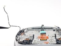
The battery is positioned above the screen and lens assembly and requires significant disassembly in order to reach it.
Note: You'll need a long PH00 bit or a dedicated PH00 screwdriver to remove some recessed screws.
Ce dont vous avez besoin
-
-
Hold the power button for three seconds to fully turn off your headset.
-
-
-
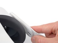
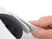
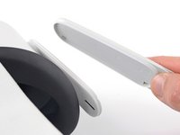
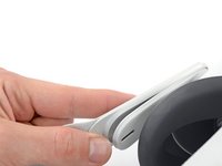
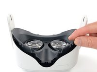
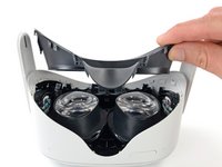
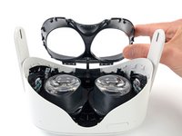
Grasp and pull on the nose section of the facial interface to unclip it from the headset.
-
-
-
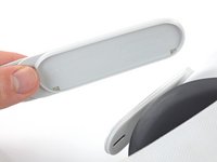
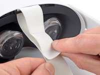
Use your fingers to grasp the right strap near the headset.
-
Peel the right strap away from the headset arm to unclip it.
-
-
-
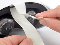
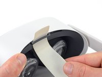
Unthread the top strap from its bracket.
-
Remove the head strap.
-
-
-
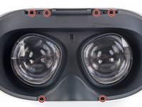
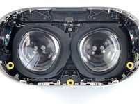
Use a Torx T2 driver to remove the six 3.5 mm‑long screws securing the eyepiece trim.
-
-
-
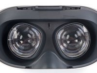
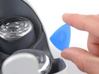
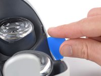
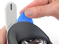
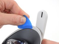
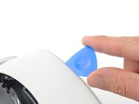
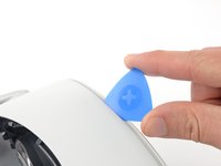
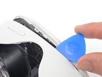
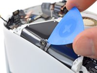
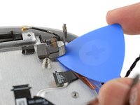
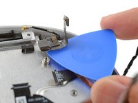
Insert an opening pick into the seam between the eyepiece trim and white outer shell, near the nose cutout.
-
-
-
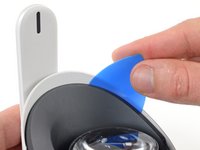
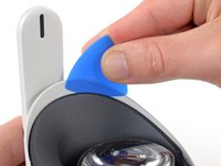
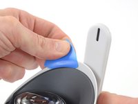
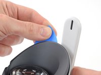
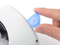
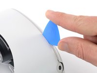
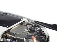
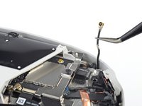
Lift the eyepiece trim slightly and tilt it towards the top edge of the headset.
-
Set the trim down on your work surface, making sure not to strain the cable.
-
-
-
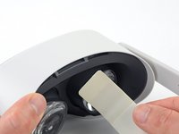
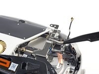
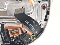
Use the point of a spudger to flip open the black lock tab on the ZIF connector securing the face sensor cable.
-
-
-
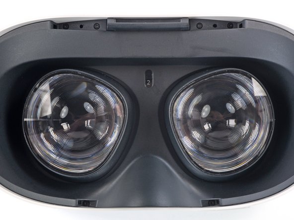
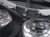
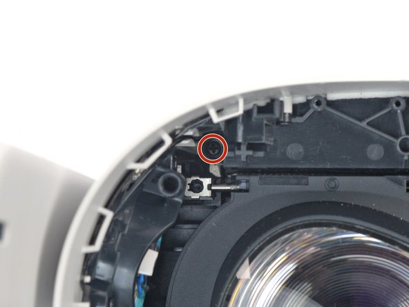
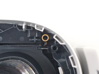
Make sure the lens spacing matches the spacing indicator. This allows the indicator peg to sit correctly in its notch.
-
If the lens spacing doesn't match the indicator, manually adjust the lens with your fingers.
-
-
-
Thread your fingers through the eyepiece trim’s eyeholes and grasp the edges of the sensor cable.
-
Slide the sensor cable into the socket until the first set of tabs rests in the socket. This should flip the lock tab down partially.
-
Use a spudger to press the lock tab down towards the cable to lock it in place.
-
-
-
Use a Phillips screwdriver to remove the five 7.7 mm‑long screws securing the front cover to the headset:
-
One recessed in the top-left corner
-
One recessed in the top-right corner
-
Three along the lower edge
-
-
-
Insert an opening pick into the seam between the bottom edge of the front cover and the headset.
-
Pry with the opening pick to release the front cover clips.
-
-
-
Outil utilisé dans cette étape :Tweezers$4.99
-
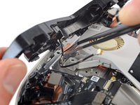
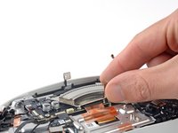
Use a pair of tweezers to grasp the metal neck of the top-right antenna cable.
-
Lift the antenna connector straight up to disconnect it.
-
Guide the antenna cable out of its metal clip holding it in place.
-
-
-
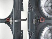
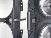
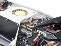
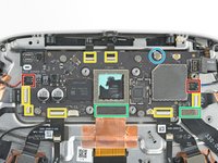
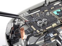
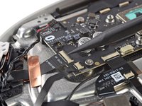
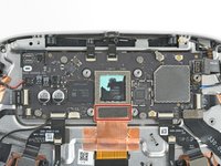
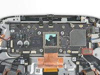
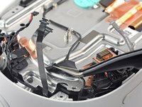
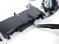
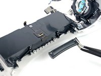
Use a Phillips screwdriver to remove the three screws securing the battery cable bracket:
-
One 4.4 mm‑long screw
-
Two 2.3 mm‑long screws
-
-
-
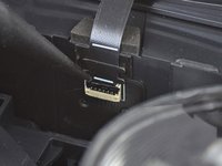
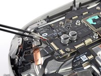
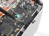
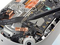
Use a spudger to pry up and disconnect the battery press connector from the motherboard.
-
-
Outil utilisé dans cette étape :Tweezers$4.99
-
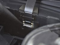
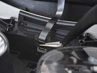
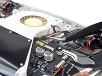
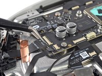
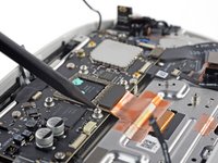
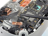
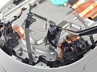
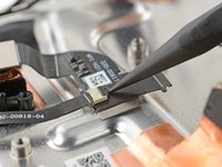
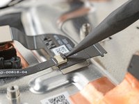
Insert one arm of a pair of tweezers under the metal neck of the black antenna cable near the fan assembly.
-
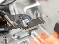
Lift the antenna connector straight up to disconnect it.
-
Guide the antenna cable out of its metal clip holding it in place.
-
-
-
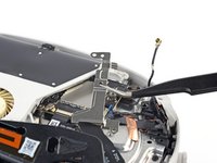
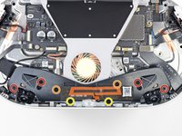
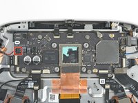
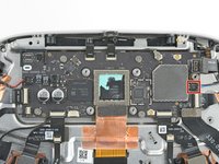
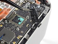
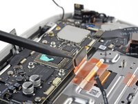
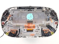
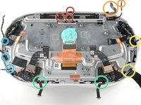
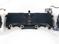
Use a Phillips screwdriver to remove the eight screws securing the antenna assembly to the headset:
-
Four 4.4 mm‑long screws
-
Two 4.8 mm‑long screws
-
Two 10.7 mm‑long screws
I love the way you color-coded each set of screws to help with organization!
-
-
Outil utilisé dans cette étape :Tweezers$4.99
-
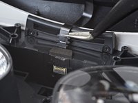
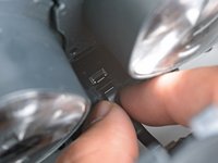
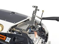
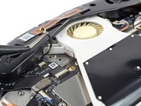
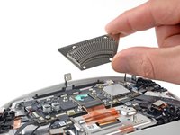
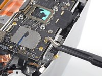
Use tweezers to grab the fan connector and carefully slide it out of its socket.
-
-
-
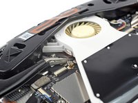
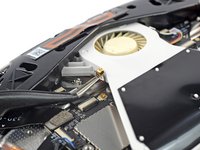
Use the point of an opening pick to loosen the adhesive securing the LED flex cable from the top of the fan assembly.
-
-
-
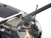
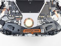
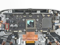
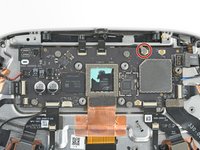
Remove the two screws securing the fan assembly to the headset:
-
One 4.4 mm‑long Phillips screw
-
One 3.6 mm‑long Torx T2 screw
-
-
-
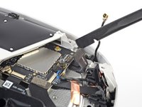
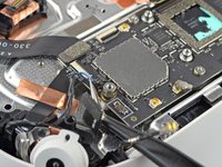
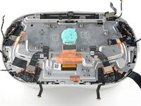
Use a Phillips screwdriver to remove the four 2.3 mm‑long screws securing the heat sink to the motherboard.
-
-
-
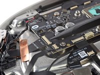
Two speaker connectors
-
Seven ZIF connectors
-
Two press connectors
-
One antenna connector
-
-
Outil utilisé dans cette étape :Tweezers$4.99
-
Use tweezers to grip the left speaker cables at the base of their motherboard connector.
-
Lift the connector gently straight up to disconnect it.
-
-
-
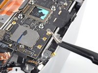
Use tweezers to gently peel the black tape covering the two top flex cables.
Be careful not to pull the cable from the connector. Take extra care on this step.
-
-
-
Use a spudger to pry up and disconnect the display cable.
-
-
-
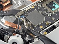
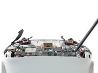
Remove the five screws securing the motherboard to the headset:
-
Four 3.8 mm‑long Phillips screws
-
One 6 mm‑long 3.5 mm hex standoff screw
-
-
Outil utilisé dans cette étape :Tweezers$4.99
-
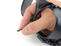
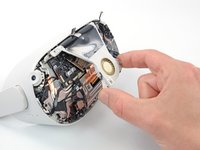
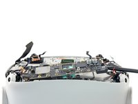
Use your fingers or tweezers to peel and remove the two camera covers from the top cameras.
-
-
-
Peel and remove the black tape covering the antenna cable.
-
-
-
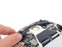
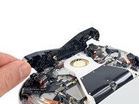
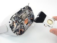
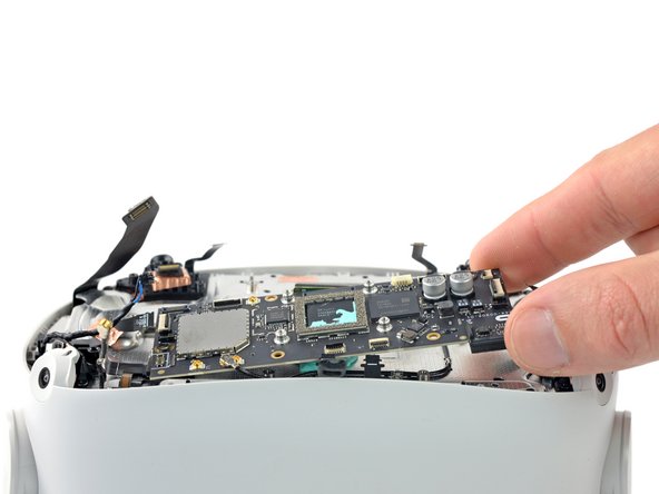
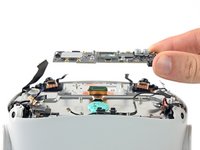
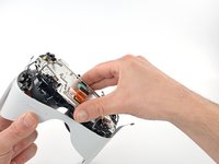
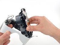
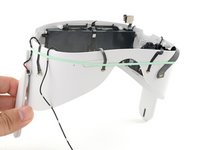
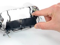
Grasp the screen and lens assembly with your fingers.
-
Slowly lift and separate the assembly from the outer shell, taking care to reposition any cables that get in the way.
-
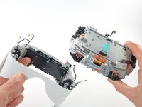
Remove the screen and lens assembly.
-
-
-
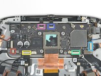
Three cables along the top edge—two flex cables and one LED flex cable
-
Two cables in the top right corner—the battery connector and an antenna cable
-
Two cables along the right edge—an antenna cable and a wide flex cable
-
Two flex cables along the bottom edge
-
Three cables along the left edge—one antenna cable, one flex cable, and one speaker cable
-
-
-
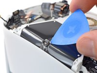
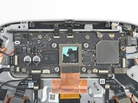
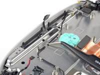
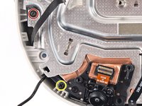
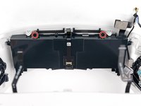
Use a Phillips screwdriver to remove the six 4.5 mm‑long screws securing the battery to the outer shell:
-
Two along the front edge
-
Four along the back edge
-
-
Outil utilisé dans cette étape :Tweezers$4.99
-
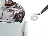
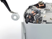
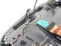
Use your fingers or tweezers to remove the top strap bracket.
-
-
-
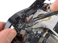
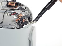
Slide an opening pick under the face sensor interconnect cable to loosen the adhesive securing it to the battery.
-
Remove the sensor interconnect cable.
-
-
-
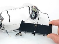
Only the headset battery remains.
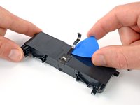
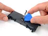
You can remove the three T2 screws and to lift the metal cover off of the battery assembly to access the cell. The cell is secured with weak adhesive. Pour a bit of IPA into the tray and after a few minutes, use picks to pry the cell free of tray. Take your time with this to avoid cracking the tray.
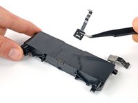
Once the cell is free, you can carefully peel away the strip of black tape from the top of the cell which allows you to slide the plastic cap off the cell and expose the main positive and negative terminals that directly connect the cell to the protection pcb. This provides a safer way to test the cell.
You can detach the cell from the protection board and replace it with one that will fit the tray or try to charge it.
My cell measured 2.0V. I am attempting to use a cheap TP4056 module to charge the cell up to full. A TP4056 will trickle charge a low cell up to about 3.5V and then will switch to normal charging rate up to 4.2V. I'll post a follow up comment if I have any success with this. -


To reassemble your device, follow these instructions in reverse order.
For optimal performance, after completing this guide, calibrate your newly installed battery.
Take your e-waste to an R2 or e-Stewards certified recycler.
Repair didn’t go as planned? Try some basic troubleshooting, or ask our Answers community for help.
Annulation : je n'ai pas terminé ce tutoriel.
15 autres ont terminé cette réparation.


11 commentaires
Life is too short.
I followed this to change the battery in my son's headset amd I have to say it was a life saver. Very well written and detailed, the photos and coloured circles were of particular help. Thanks for the effort - I'm about to use it again to replace the motherboard! Really frustrating that with a few simple design changes Meta could have made this a five minute job, but well done for helping us all out! :)
This was a well written and very thorough how to guide that tool a lot of dedication and I commend you for it. I am contemplating taking on this endeavor on behalf of my adult son who was gracious enough to allow me to use his machine and I am now a huge fan, just in time for the battery to wear out. Still debating if I will attempt but know for sure I would not even begin.to consider it without your guide. Thank you for such a selfless endeavor!
Many thanks!!!
where do you get the replacement battery? Thank you!
I found a couple on Amazon, which I imagine you have by now as well, but there may be better options available.
Jon R -
Fantastic guide. Really easy to follow. I struggled with the tape on step 41 and accidentally pulled a cable out before releasing the clip so take care on this step.
Mmm osea las baterías están justo detrás de las pantallas, si explotan dios no lo quiera adiós a los ojos ?!