Introduction
Suivez ce tutoriel pour remplacer une carte mère défectueuse ou endommagée dans la Nintendo Switch Lite.
La Switch Lite utilise des vis JIS, mais à la rigueur vous pouvez utiliser un tournevis cruciforme. Faites très attention à ne pas abîmer les vis. Les embouts cruciformes d'iFixit sont conçus pour être compatibles avec les vis de style JIS.
Remarque : cette procédure nécessite le retrait de la plaque de protection et du dissipateur de chaleur. La pâte thermique devra être nettoyée des deux composants, ainsi que du processeur, et réappliquée avant de réinstaller la plaque de protection et le dissipateur thermique.
Ce dont vous avez besoin
-
Outil utilisé dans cette étape :Magnetic Project Mat$19.95
-
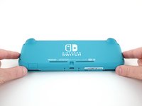
Prenez un tournevis Y00 pour dévisser les quatre vis de 6,3 mm de long qui fixent la coque arrière.
-
-
-
À l'aide d'un tournevis cruciforme, dévissez les vis suivantes qui fixent la coque arrière :
-
Deux vis de 3,6 mm de long en haut de l'appareil
-
Deux vis de 3,6 mm de long en bas de l'appareil
I accidentally stripped the back screw and now I can't open it. I removed all the other screws. What should I do?
-
-
-
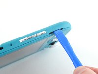
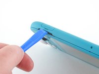
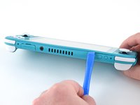
Insérez un outil d'ouverture dans la grille du haut-parleur gauche en bas de l'appareil.
-
Faites pivoter l'outil d'ouverture pour défaire les clips qui fixent la coque arrière.
-
-
-
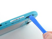
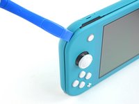
Faites glisser l'outil d'ouverture le long du coin inférieur gauche pour ouvrir les clips du côté gauche de l'appareil.
-
-
-
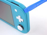
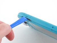
Insérez un outil d'ouverture dans la grille du haut-parleur droit en bas de l'appareil.
-
Faites pivoter votre outil pour détacher les clips.
-
-
-
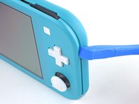
Faites glisser l'outil d'ouverture le long du coin inférieur droit pour défaire les clips du côté droit de la console.
-
-
-
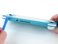
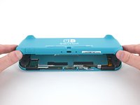
Soulevez le bord inférieur de la coque arrière, à la manière d'un livre.
-
Enlevez la coque arrière.
-
-
-
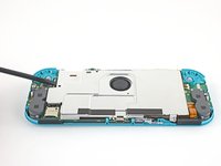
Avec un tournevis JIS 000 ou un tournevis cruciforme iFixit PH 000, dévissez les quatre vis suivantes :
-
Trois vis de 3,1 mm
-
Une vis de 4,5 mm
There are four screws instead of three mentioned
With how easy it seems to be to do serious damage with the next few steps, I figured I'd say that realistically you can skip steps 9-13 when doing this repair. While they provide a bit of extra security by disconnecting the battery, the left stick is completely accessible and replaceable without touching the heat shield or anything underneath (And steps 17 and 18 disconnect power from the daughter board regardless).
i stripped a &&^&^$^ screw
Well I actually removed the screw right next to the 4.5 screw. I did not realize it till my son showed me why the plate wouldn't release. Ha ha, it's funny now but yeah not a big deal. I could have bent it badly assuming I took all screws out though. For anyone reading this before going in. 👍
-
-
-
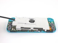
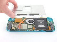
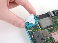
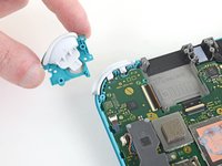
Avec une spatule ou vos doigts, soulevez la plaque de protection vers le haut et sortez-la de la console.
-
Retirez la plaque.
What type of Thermal Paste would you guys recommend? I clicked on the picture but nothing.
Personnaly i use some Mx-6 from Artic, really good quality/price, never have to complain.
Nothing -
-
-
-
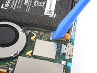
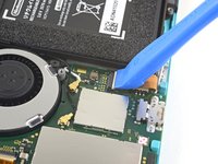
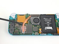
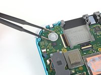
Prenez un outil d'ouverture ou votre ongle pour retourner le petit clapet qui verrouille le connecteur ZIF de la nappe d'interconnexion de la carte mère.
The clip broke off when trying to remove this cable. Audio only works through headphones and the display now won’t turn on after the clip broke. Does anyone know where I could get a clip or how I could fix it without it?
Mi è successa la stessa cosa è non so come ripararla! Chissà se c’è un modo!
-
-
-
-
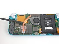
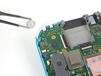
Avec une pincette, faites glisser la nappe d'interconnexion hors de sa prise sur la carte mère.
I turned the unit off beforehand, I used tweezers just like the instructions said (ifixit branded) , my device sparked and now it won’t turn back on
The flap came off is it important or is there a way t fix it?
We're you able to get it working without the white flap? My screen is not working after putting it back together and i noticed this white flap was falling off
Did you get it working without the white flap? Everything on the switch works fine except for audio going through headphones and the display not turning on.
do not use metal sharp pointed tweezers! you will rip your ribbon cable. Use the inside of a Bic type pen or something else dull and plastic to pull the cable away by putting the pen part where the first bend is.
Maybe tape the Tweezers or smear some hot glue on them to insulate them to save you time and money.
Maybe put all the Warnings at the start of the guide as well. We fix it geeks tend to get excited when fixing things 😁
-
-
-
Prenez la pointe de la spatule pour soulever le connecteur de la batterie tout droit hors de sa prise sur la carte mère.
Caution the connector may not be properly soldered onto the motherboard. For me it snapped off the pins and now have to find a place to get that fixed if even possible. may have bricked it.
Yup, broke the connector right off the motherboard. Thanks, ifixit -_-
I backed out when I reached this point. I couldn't risk damaging it. Do u just need to pull it up? Did you mean that it might have been soldered shut below?
You should just need to pull straight up, but make sure you’re pulling on the wires or the gray plug—do not pull on the black socket or it can snap off of the motherboard.
With how easy it seems to be to do serious damage at this point, I figured I'd say that realistically you can skip steps 9-13 when doing this repair. While they provide a bit of extra security by disconnecting the battery, the left stick is completely accessible and replaceable without touching the heat shield or anything underneath (And steps 17 and 18 disconnect power from the daughter board regardless).
just broke my connector... ifixit PLEASE put a warning on how fragile the solder on this connector is.
Note for this step, you do not need to apply a lot of force. I used two tools here: small screwdriver to hold down the black base, and one side of fine-tipped tweezers to get under all 3 wires. Gently, push down on the tweezers to push the wires upwards, which should force the gray connector up and off the base. It did not take a lot of force. Take your time and it will be fine. Again, like others have said, do NOT pull or pry up the black base.
-
-
-
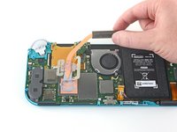
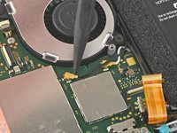
Servez-vous de l'extrémité plate d'une spatule ou de vos doigts pour décoller la mousse qui adhère légèrement au ventilateur.
When reassembling, the foam may fold down between the fan and heatsink, blocking airflow. Gently lift the foam back up on top of the fan. The adhesive film should hold the foam together.
Is removing the heat sink absolutely necessary?
It’s not necessary, but it makes it much easier to remove and replace the game card reader, since the heat sink partially covers the connector.
Not really…….. I never remove it. It slides out quite easily once disconnected.
-
-
-
Avec un tournevis JIS 000 ou un tournevis iFixit PH 000, dévissez les trois vis de 3 mm qui fixent le dissipateur thermique à la carte mère.
Non le tre ventole ma le tre viti
Grazie per avercelo segnalato! Ho apportato la modifica. iFixit è una wiki, quindi ogni utente può modificare le pagine: se trovi altri errori in futuro, sentiti libero di fare la modifica tu stesso!
-
-
-
Avec une spatule ou vos doigts, soulevez le dissipateur thermique pour le détacher de la carte mère et le retirer.
16.5 remove cartridge / headphones jack……….
My kit did not come with thermal paste..
-
-
-
Avec un tournevis JIS 000 ou un tournevis cruciforme iFixit PH 000, dévissez les deux vis de 4,5 mm qui fixent le module de la gâchette droite à la carte mère.
I think a whole step to remove the game card reader and speaker jack was skipped here…
yes, just found that sadly these comments do not show unless we click on the , which is unhelpful
also, you need to remove the left trigger button
-
-
-
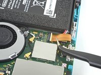
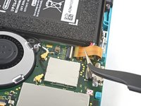
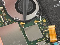
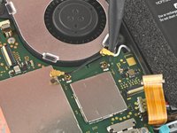
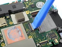
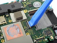
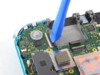
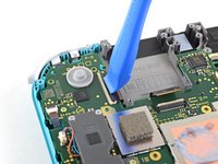
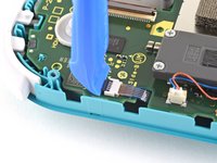
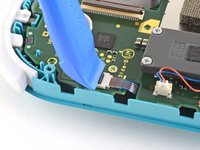
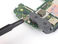
Faites levier avec la pointe d'une spatule sur le câble d'antenne noir pour le sortir de sa prise sur la carte mère.
-
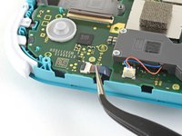
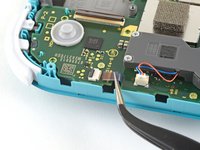
Répétez la procédure pour le câble d'antenne blanc.
-
-
-
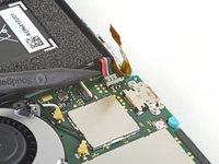
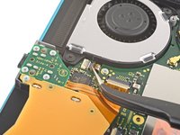
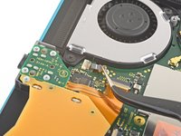
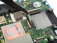
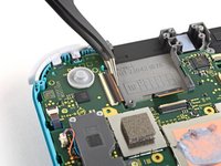
Servez-vous d'un outil d'ouverture ou de votre ongle pour retourner le petit clapet de retenue du connecteur ZIF de la nappe du ventilateur.
-
-
-
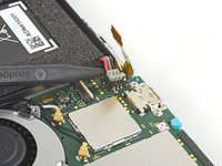
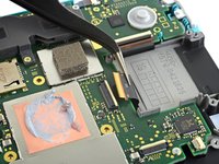
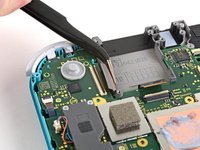
Faites glisser la nappe du ventilateur hors de son connecteur sur la carte mère à l'aide d'une pincette.
There’s a step missing after this to remove the screws that hold the orange game cartridge slot. Those 7 screws have to be undone and the ribbon unclipped first before moving on to the next step.
Good Looking out!
-
-
-
Avec un outil d'ouverture ou votre ongle, retournez le petit clapet de retenue du connecteur ZIF de la nappe de l'écran.
skipped a step or two about removing the golden piece in the photo above, and the other little board
If I broke the clasp on the ZIF connector can I elec tape it down?
What did you do to fix it if the ZIF connector broke?? Mine did too and I worry that is why the screen won’t turn on now
Missing the card reader + audio jack board removal. Just remove the 4 screws around the audio jack + 3 screws around the card reader and disconnect the ZIF connector from the motherboard.
-
-
-
À l'aide d'un outil d'ouverture ou de votre ongle, retournez le petit clapet qui verrouille le connecteur ZIF de la nappe de la vitre tactile.
-
-
-
À l'aide de votre outil d'ouverture ou de votre ongle, retournez le petit clapet de retenue du connecteur ZIF de la nappe du joystick droit.
-
-
-
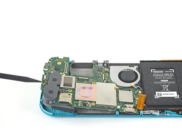
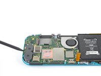
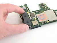
Avec un tournevis JIS 000 ou un tournevis iFixit PH 000, dévissez les six vis suivantes qui fixent la carte mère :
-
Trois vis de 3,1 mm
-
Trois vis de 4,5 mm
how to get the c port off
When re-assembling, be sure the fan cable (step 25) is completely pulled through prior to tightening the screw that’s right next to it.
-
-
Outil utilisé dans cette étape :Tweezers$4.99
-
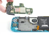
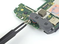
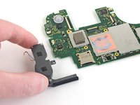
Utilisez une pincette ou vos doigts pour tirer le câble du haut-parleur droit vers le haut et hors de sa prise sur la carte mère.
-


Pour remonter votre appareil, suivez ces instructions dans l'ordre inverse.
Déposez vos déchets électroniques dans un point de recyclage certifié.
La réparation ne s’est pas déroulée comme prévu ? Consultez nos conseils basiques de diagnostic ou notre Forum pour obtenir de l’aide.
Pour remonter votre appareil, suivez ces instructions dans l'ordre inverse.
Déposez vos déchets électroniques dans un point de recyclage certifié.
La réparation ne s’est pas déroulée comme prévu ? Consultez nos conseils basiques de diagnostic ou notre Forum pour obtenir de l’aide.
Annulation : je n'ai pas terminé ce tutoriel.
22 autres ont terminé cette réparation.
Merci à ces traducteurs :
100%


Ces traducteurs nous aident réparer le monde ! Vous voulez contribuer ?
Commencez à traduire ›

7 commentaires
It stops at motherboard removal, is there a section for replacing the USB charging port on the switch lite?
I have a working motherboard but it is missing one of the resistors (see the green square). How do I find out the value of this resistor? The resistor is situated to the left of the main chip, just below the microSD card slot, if the USB-C port is facing downward.
All my screws got stripped any ideas on how to remove?
Almost A Mammal - Réponse
A Y0 screwdriver seemed to work better for me.
Tommy Morrill - Réponse
What type of screw driver do I use to un screw the screws and which way
Luca Capito - Réponse
Y 0.6 was all I had but it seemed to fit perfectly
Trevor - Réponse
Like really snug? I've gotten away with using Drivers either bigger or smaller but I hate doing it. But if 0.6 is the exact size I need, then I'll get that. I don't wanna strip my client's Switch Lite's screws.
Vincent Valodze -