
Démontage du boitier du Canon Selphy CP910
Introduction
Passez à l'étape 1Il peut être nécessaire d'ouvrir le Canon Selphy CP910 afin de remplacer les pièces de l'imprimante. Pour plus d'informations sur les problèmes de dépannage avec le Canon Selphy CP910, accédez à Canon Selphy CP910 Dépannage.
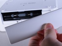
Retirez tous les composants externes tels que la cassette de papier, cartouche d'encre et les cartes mémoire avant de démonter l'appareil.
Ce dont vous avez besoin


-
-
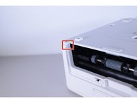
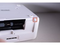
Retournez l'imprimante.
-
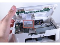
Utilisez le foret PH1 pour retirer les trois vis de 8 mm au milieu de la plaque arrière.
-
-


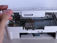
Pour remonter votre appareil, suivez ces instructions en sens inverse.
Pour remonter votre appareil, suivez ces instructions en sens inverse.
Annulation : je n'ai pas terminé ce tutoriel.
2 autres ont terminé cette réparation.
Merci à ces traducteurs :
100%

Ces traducteurs nous aident réparer le monde ! Vous voulez contribuer ?
Commencez à traduire ›
Équipe

UW Tacoma, Team 1-6, Rose Winter 2016 Membre de l'équipe UW Tacoma, Team 1-6, Rose Winter 2016
UWT-ROSE-W16S1G6
4 membres
10 tutoriels rédigés
3Commentaires sur le guide
I read this recipe thinking that the 64 bit driver kit should contain all the necessary tools, but there is no way I can reach to the corner screws with it (step 2). It would be useful to have the narrow screwdriver also listed in the tools overview.
Be carefull!!! almost all this part is connected by ribbon and small plastic for tightened the cable and it is not a socket so you can only repair it for once or twice before the small blue plastic is separated from the cable and without the plastic the cable can not be plug to the board, and the gold plate is very frail could be broken easily!!! And the worst part is the cable which is tightened by switch at the backside of motherboard can be released accidentally such as in the delivery and make the photo print just a blank page, because mine now lcd and power button cable are broken and the worst part because don’t know about the cable, just ruined the head unit with the ink sheet and now photo print can’t be used anymore because it is dirty, IF YOU FEEL ANY PROBLEM WITH THIS SELPHY, DON’T EVER OPEN IT EVEN WITH PROFESSIONAL TECHNICIAN, JUST SELL IT!!
This “disassembly” is actually unfinished business…
1. I would like to point out, that for step 2 you really need a thin and long screw driver, otherwise you will have no luck with the corner screws, as stated above!
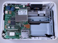
2. after step 4 there should follow taking out the motherboard, then removing the printing unit from the body, removing some more parts to finally clean the rolls and the printer head. That can solve the “white line” issues.
3. There’s a video on YT, not well done, but one gets the point on how to do it.