Aller au contenu principal
Flash Motherboard

Flash Motherboard

Jakub

Jakub et 6 autres contributeurs

Dernière mise à jour le August 13, 2018

Aucune estimation
Difficile
Tutoriel vedette

If your flash settings are set correctly but your camera does not flash, you will need to replace the flash motherboard. First, you will need to remove the front and back covers. Once that is complete, you will have access to the flash motherboard.

Ce dont vous avez besoin

  1. Flash Motherboard, Front and Back Covers: étape 1, image 1 de 3 Flash Motherboard, Front and Back Covers: étape 1, image 2 de 3 Flash Motherboard, Front and Back Covers: étape 1, image 3 de 3
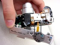
    • Unscrew a total of 6 4.45 mm phillips head screws using a #00 phillips head screwdriver.

    • There are 2 screws on the left side (when looking at the front of the camera).

    • There are 3 screws on the bottom

    • There is 1 screw on the right side

  2. Flash Motherboard: étape 2, image 1 de 1
    • Turn to the bottom of the camera.

    • Open the memory card cover by sliding the "CARD/BATT." button up, and then pulling the cover to the left.

  3. Flash Motherboard: étape 3, image 1 de 1
    • This is what the SD card/battery compartment looks like when opened.

    • Remove one 4.45mm phillips head screw from the SD card/battery compartment using a #00 phillips head screwdriver.

  4. Flash Motherboard: étape 4, image 1 de 2 Flash Motherboard: étape 4, image 2 de 2
    • Gently remove the front cover away from the camera body.

    • Tip: Start by loosening the teeth on the left side of the camera next to the battery compartment.

  5. Flash Motherboard: étape 5, image 1 de 1
    • The camera should look like this once the front cover is removed.

  6. Flash Motherboard: étape 6, image 1 de 3 Flash Motherboard: étape 6, image 2 de 3 Flash Motherboard: étape 6, image 3 de 3
    Outil utilisé dans cette étape :
    Tweezers
    $4.99
    • Start from the battery compartment and remove the back cover.

    • Caution: Do not tug on the back cover after it is removed. This could tear the ribbon attaching the back cover to the camera body.

    • Remove the connecting ribbon from the body of the camera using a pair of tweezers.

  7. Flash Motherboard: étape 7, image 1 de 1
    • Once the ribbon connecting the back cover is removed, the back of the camera body should look like this.

  8. Flash Motherboard, Flash Motherboard: étape 8, image 1 de 1
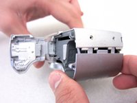
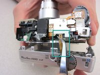
    • Turn to the front of the camera.

    • Find the flash motherboard located behind the flash assembly on the top right.

  9. Flash Motherboard: étape 9, image 1 de 1
    • Use a soldering iron and a desoldering wick to disconnect the wires from the marked locations.

    • Once the cables are disconnected, you are now ready to install a new motherboard.

Conclusion

To reassemble your device, follow these instructions in reverse order.

4 autres ont terminé cette réparation.

Jakub

Membre depuis le 04/19/11

134 Réputation

2 tutoriels rédigés

Équipe

Cal Poly, Team 8-6, Regan Spring 2011 Membre de l'équipe Cal Poly, Team 8-6, Regan Spring 2011

CPSU-REGAN-S11S8G6

4 membres

22 tutoriels rédigés

0 commentaires

Ajouter un commentaire

Nombre de vues :

Dernières 24 heures : 0

7 derniers jours : 2

30 derniers jours : 15

Total : 3,931