
HP Compaq 6730b Display Replacement

Introduction
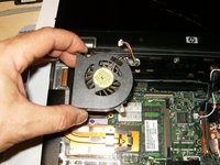
Passez à l'étape 1This laptop needed a new LCD. It is actually a straight forward task and does not require a lot of special tools. I did remove the fan since it was easier to remove one of the connectors, but it is not an absolute must, I just preferred it that way.
Ce dont vous avez besoin


-
-
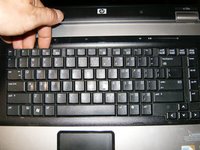
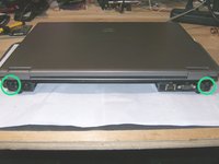
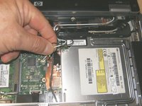
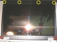
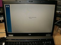
Okay, so here is a HP 6730b that was accidentally dropped. The cracks in the LCD are clearly visible on the left side of the image.
-
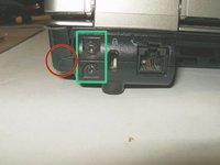
Shut down the computer. Disconnect all external devices connected to the computer. Disconnect the power from the computer by first unplugging the power cord from the AC outlet and then unplugging the AC adapter from the computer.
-
Close the screen and turn the computer over. Remove the memory/WLAN module compartment cover by loosening the Phillips 2.0×5.0 "captive" screw. They are secured by a spring clip at the back, so they will not be easily removed. All that is required is to loosen those.
-
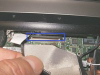
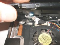
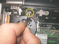
Disconnect the WLAN antenna cables from the terminals on the WLAN module. The black cable is connected to the WLAN module “Main” terminal. The white cable is connected to the WLAN module “Aux” terminal.
-
-
-
Remove the battery. Slide the locking tab to the left and release the battery.
-
Loosen the three Phillips 2.5×9.0 captive screws that secure the keyboard to the computer.
-
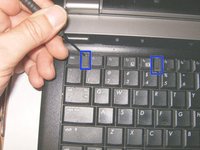
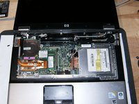
Turn the computer display-side up, with the front toward you. Open the computer as far as possible. There are four retention tabs that hold the keyboard down.
-
-
-
Use a small screwdriver, or other instrument, to slide the four tabs in a downward direction toward the palmrest.
-
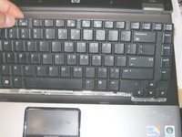
Gently lift the keyboard up from the display side,
-
and tilt it toward the front of the computer. Do not lift it up to fast or to high, the keyboard ribbon cable is still connected.
-
-
-
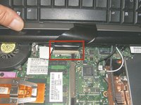
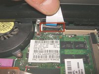
Here is the keyboard ribbon cable seated in the zero insertion force (Zif) connector.
-
Release the ZIF connector to which the keyboard cable is attached, by lifting the clasp in an upward direction. Disconnect the keyboard cable from the system board.
-
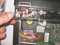
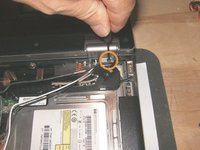
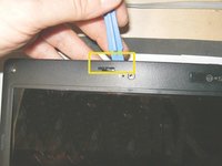
Release the Zif connector to which the power button board cable is connected, by lifting the clasp of the Zif connector in an upward direction.
-
-
-
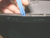
Lift the left and right sides of the switch cover until it detaches from the computer, but do not yet try to remove it.
-
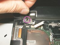
The LED board cable is still attached, disconnect it from the Zif connector by simply pulling it out in an upward direction.
-
With both ribbon cables disconnected, remove the switch cover.
-
-
-
-
Close the computer and position it with the rear panel toward you. Remove the four Torx T8 M2.5×9.0 screws that secure the display assembly to the computer.
-
There are two on the left side,
-
Notice cracked bottom case from impact, no sequela from it.
-
and two screws on the right. Note the slots in the screw heads. these screws can also be removed with a flat tip screwdriver.
-
-
-
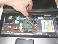
Position the computer with the front toward you and open the computer as far as possible.
-
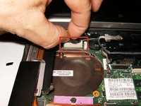
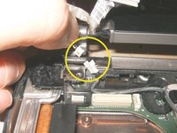
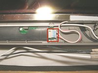
Disconnect the display panel cable from the system board, by pulling the connector from the socket. Do not pull the cable, but pull on the connector.
-
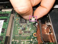
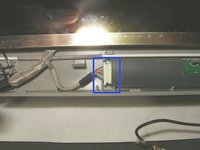
Disconnect the camera cable from the system board.
-
-
-
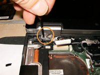
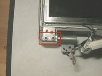
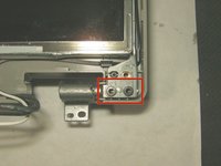
Remove one of the two T8 M2.5×9.0 screws that secure the display assembly to the computer. The screw on the left display assembly hinge secures a display panel cable ground loop.
-
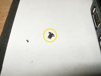
The second screw on the left side is only 3mm in length but must be removed as well
-
Pull the two antenna cables out from the bottom of the case.
-
-
-
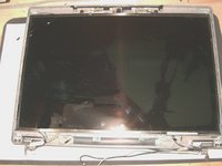
Disconnect the camera cable. The display can now be separated from the bottom case.
-
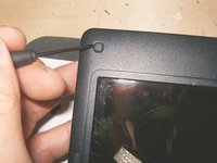
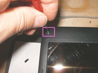
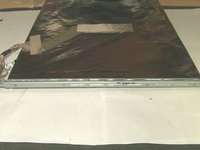
There are four beveled rubber screw covers on the display bezel top edge.
-
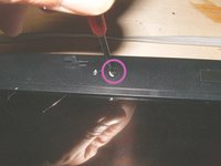
and two flat rubber screw covers on the display bezel bottom edge
-
These are simply glued in. Use a small screwdriver or similar instrument to remove them
-


To reassemble your device, follow these instructions in reverse order.
To reassemble your device, follow these instructions in reverse order.
Annulation : je n'ai pas terminé ce tutoriel.
13 autres ont terminé cette réparation.

Équipe

6 commentaires
I would like to express my thanks to the author of this guide - the instructions are extremely comprehensive and the pictures are very helpful. As with the earlier contributor, I had to move across the cable from my old screen to the new one, but much more importantly thanks to the guidance set out above I once more have a laptop I can use. Thanks again!
This is terrific! I followed it to replace a broken hinge on my laptop, and everything worked well. Replacing the camera/mic cable upon reassembly is a very fiddly operation . Other than that this guide is flawless. Thanks!
I just completed this replacement today and this guide was a great help. The steps were easy to follow and made the process smooth and painless. I have added one small correction to the text in Step 10 c. The connector shown is for the pair of microphones located in the top of the bezel. Thanks for the help.
loved this thank you.