Aller au contenu principal
Interlink VP4550 Circuit Board Replacement

Interlink VP4550 Circuit Board Replacement

custer78

custer78 et 12 autres contributeurs

Dernière mise à jour le May 7, 2024

15 minutes
Facile
Photos d’action
Nécessite plus d'images
Meilleure introduction

To replace the Circuit Board on an Interlink VP4550 wireless presenter remote requires only 6 easy steps. The Circuit Board controls all of the functions in the remote therefore can be the reason for an unresponsive remote. This guide will show you how to replace the circuit board in the safest and easiest way possible. Below is a step-by-step process on how to disassemble the remote, install the circuit board, and reassemble it all.

Ce dont vous avez besoin

Outils

Afficher plus…

  1. Interlink VP4550 Circuit Board Replacement, Case: étape 1, image 1 de 3 Interlink VP4550 Circuit Board Replacement, Case: étape 1, image 2 de 3 Interlink VP4550 Circuit Board Replacement, Case: étape 1, image 3 de 3
    • Turn the phone over to where the battery compartment resides.

    • Remove the battery compartment door by pushing down on the door with your thumbs and sliding the door off of the bottom of the device.

    • Remove battery.

  2. Interlink VP4550 Circuit Board Replacement: étape 2, image 1 de 3 Interlink VP4550 Circuit Board Replacement: étape 2, image 2 de 3 Interlink VP4550 Circuit Board Replacement: étape 2, image 3 de 3
    • Use a Phillips #0 screwdriver to remove the screw in the middle of the battery compartment.

    • Pry open the case body with the plastic opening tool. Start at the bottom of the device and work toward the top. You will hear a "click" sound as the sides open.

  3. Interlink VP4550 Circuit Board Replacement: étape 3, image 1 de 2 Interlink VP4550 Circuit Board Replacement: étape 3, image 2 de 2
    • There is a wire connector linking the front and the back of the device.

    • Carefully pull the wire connectors out of the white connector gauge to completely separate the front and back pieces.

  4. Interlink VP4550 Circuit Board Replacement: étape 4, image 1 de 2 Interlink VP4550 Circuit Board Replacement: étape 4, image 2 de 2
    • The power button may fall off when you separate the front and back of the device. This can simply be placed back when reassembling.

    • Find the lever on the right side of the back half of the device.

    • Insert the tip of the lever into the square indent on the underside of the button.

  5. Interlink VP4550 Circuit Board Replacement, Circuit Board: étape 5, image 1 de 1
    • Avoid picking up the front of the device as you work so that loose parts will not shift.

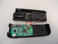
    • Use a Phillips #0 head screwdriver to remove two screws; one on either side of the circuit board.

  6. Interlink VP4550 Circuit Board Replacement: étape 6, image 1 de 1
    Outil utilisé dans cette étape :
    Tweezers
    $4.99
    • Slide the circuit board down from the tab located underneath the top of the back half

    • The laser is attached to the circuit board and will slide out of its own housing as you slide out the circuit board.

    • Use tweezers to gently remove it if it doesn't come out.

Conclusion

To reassemble your device, follow these instructions in reverse order.

custer78

Membre depuis le 02/11/14

24 Réputation

1 tutoriel rédigé

Équipe

Ohio State, Team 1-1, Buehl Spring 2014 Membre de l'équipe Ohio State, Team 1-1, Buehl Spring 2014

OSU-BUEHL-S14S1G1

4 membres

3 tutoriels rédigés

0 commentaires de tutoriel

Ajouter un commentaire

Nombre de vues :

Dernières 24 heures : 1

7 derniers jours : 1

30 derniers jours : 6

Total : 295