
Nokia 6200 Classic Circuit Board Replacement
Introduction
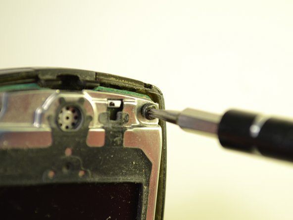
Passez à l'étape 1This guide requires that the front plate and keypad already be removed. You will have to remove 6 screws and separate the circuit board from the rest of the phone.
Ce dont vous avez besoin
Outils

-
-
Pull up on both of the clips near the bottom of the phone as shown.
-
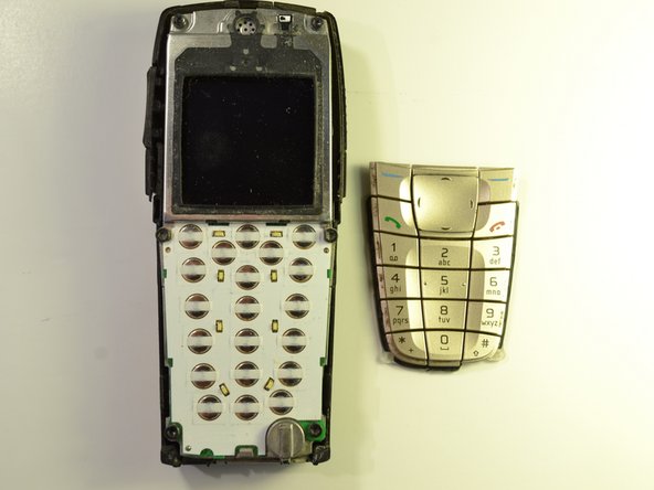
Lift off the front plate.
-
-
-
-
Separate the keypad from the phone and place aside.
-
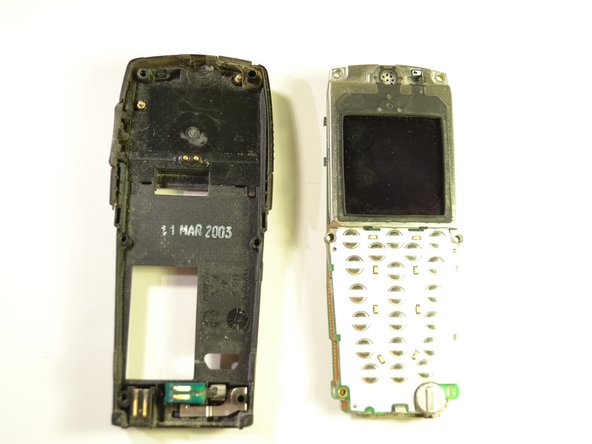
Wipe off any excess dust from where the keypad was attached to the phone.
-


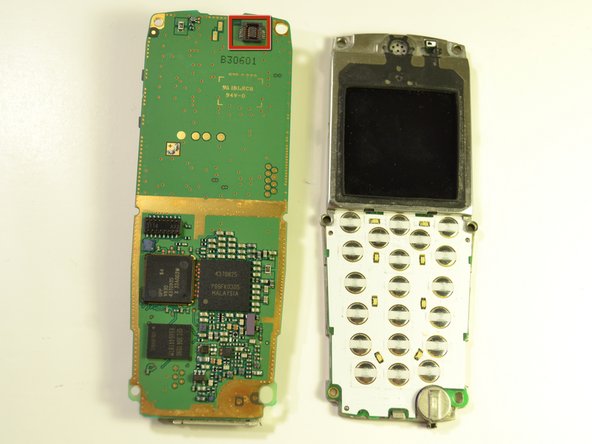


To reattach the circuit board, line up the connector at the top of the board with the back of the LCD Screen attachment. Place the two boards together, and screw in the 6 screws.
To reattach the circuit board, line up the connector at the top of the board with the back of the LCD Screen attachment. Place the two boards together, and screw in the 6 screws.
Équipe

Clemson, Team 15-5, Benson Fall 2012 Membre de l'équipe Clemson, Team 15-5, Benson Fall 2012
CLEM-BENSON-F12S15G5
3 membres
7 tutoriels rédigés