
UDI U818A Camera Assembly Replacement
Introduction
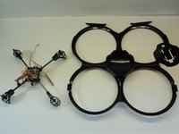
Passez à l'étape 1Replacing the camera assembly of the UDI U818A drone requires complete disassembly. The main frame is attached to the receiving board on the very inside of the drone. You will separate these two parts by unscrewing the screws in all four corners.
You should replace the camera of the drone if you notice a blurry image being received from the drone and have already troubleshoot connectivity issues, or if there is no image present at all.
Ce dont vous avez besoin


-
-
Remove the 5 mm screws connecting each propeller to the rotating post using a Phillips #000 screwdriver.
-
-
-
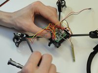
Remove four 3 mm screws connecting the electronics to the frame using a Phillips #000 screwdriver.
-
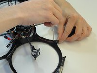
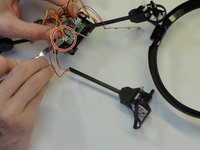
Pull the two LED bars through the dust cover and remove the thin plastic dust cover from the drone.
-
-
-
-
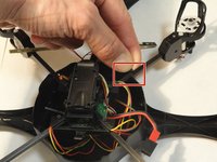
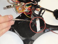
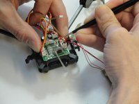
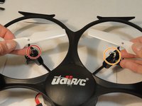
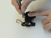
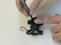
Remove four 5 mm corner screws that secure both the receiving board and the motor arm using a Phillips #000 screwdriver.
-
-
-
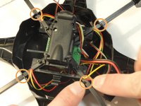
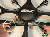
The Front Left motor identified by the Red/Blue wires is a Standard(Clockwise) spinning motor, it pairs with a White A2 propeller.
-
The Front Right motor identified by the Black/White wires is a Reverse(CounterClockwise) spinning motor, it pairs with a White B2 propeller.
-
The Back Left motor identified by the Black/White wires is a Reverse(CounterClockwise) spinning motor, it pairs with a Black B1 propeller.
-
The Back Right motor identified by the Red/Blue wires is a Standard(Clockwise) spinning motor, it pairs with a Black A1 propeller.
-
-
-
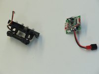
The 4 bottom connectors receive the motor power cables that are Red/Yellow wire pairs from each motor. Counting the sockets 1-4 from left to right.
-
Front Right motor connects to socket 1.
-
Front Left motor connects to socket 2.
-
Rear Left motor connects to socket 3.
-
Rear Right motor connects to socket 4.
-
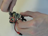
The Red/Green wire pairs from each motor power the LED to that branch, they connect to 4 of 6 sockets on the top of the receiving board. There is no sequence required.
-
The headlight LED, and underside LED bars connect to the remaining 2 sockets on the top of the receiving board. Again, no sequence is required. All LED Red/Black and Red/Green wire pairs connect to top of the receiving board.
-


Reassemble the device by following these instructions in reverse order.
Reassemble the device by following these instructions in reverse order.
Annulation : je n'ai pas terminé ce tutoriel.
2 autres ont terminé cette réparation.
Équipe

UMass Dartmouth, Team 1-4, Miles Spring 2016 Membre de l'équipe UMass Dartmouth, Team 1-4, Miles Spring 2016
UMASSD-MILES-S16S1G4
3 membres
5 tutoriels rédigés