Introduction
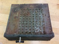
Ever been at a garage/boot/stoop/yard sale, flea market, or junk shop and seen a weird thing that looks like a cash register and a typewriter mated? These are electromechanical calculators which our dads and granddads used in the office because electronic calculators were far off in the future.
There are many of these now on eBay, but many of them are less than functional. The last time they were used was probably in the 1960s, and all the grease has probably congealed and picked up dust and twigs and things. Also, decades of being moved around and not being serviced means that parts go out of alignment or get broken by the well-meaning and the inquisitive.
Worse, the manuals and repair guides for these machines are either rare or nonexistent. My dad tells me that a man came round the office every month to maintain the calculators. It's likely that any repair information stayed inside the company.
And so, this disassembly guide will help you take this calculator to pieces so that the pieces can be cleaned, repaired, or replaced. And hopefully you'll learn a bit about the mechanisms that make these machines go.
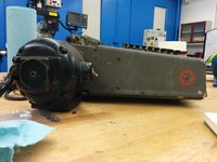
The specific calculator we're going to be taking apart is the Monroe KA. The KA is of the K series of Monroe calculators produced from 1921 to 1928, with the A meaning Automatic, that is, with an electric motor attached. This model came with various sizes of accumulator and counter, and can multiply and divide (manually) by successive addition and subtraction.
Ce dont vous avez besoin
-
-
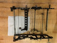
Prepare your workspace. Cover it with clean white paper or a white mat board. Light the area more than you think you'll need, and preferably from multiple directions.
-
Ready a cardboard box and lots of press-to-close bags to store the parts you pull off. Keep associated parts in their own bag, label each bag, and don't skimp on the number of bags!
-
-
-
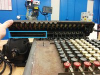
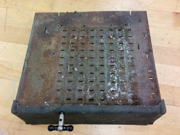
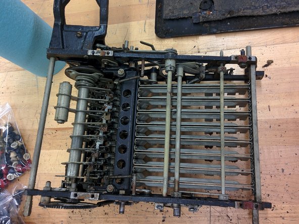
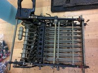
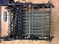
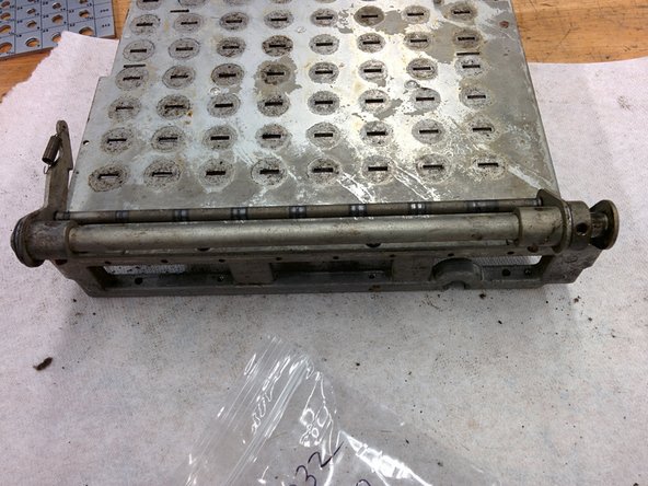
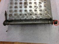
Let's first remove the carriage, which is the top part with all the number wheels on them.
-
Position the calculator so that its keyboard faces you. This orientation defines the left and right sides of the calculator.
-
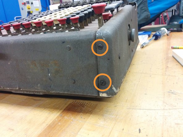
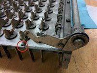
Unscrew the lower left screw on the left side of the carriage.
-
If it just keeps turning, you may need to insert a screwdriver on the other end of the shaft that this screw is connected to, the one on the lower right of the right side of the carriage. Don't turn it! Just turn the left side.
-
-
-
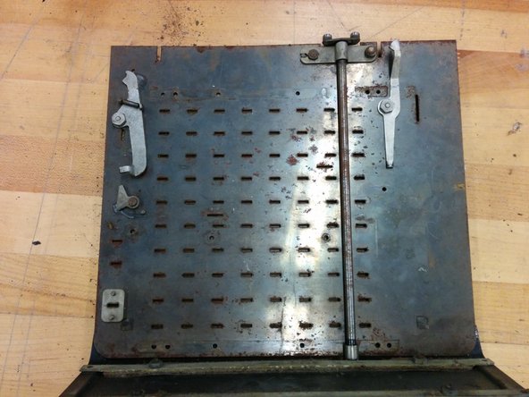
Pull back on these carriage latches and pivot the carriage up.
-
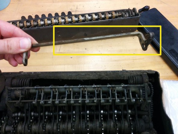
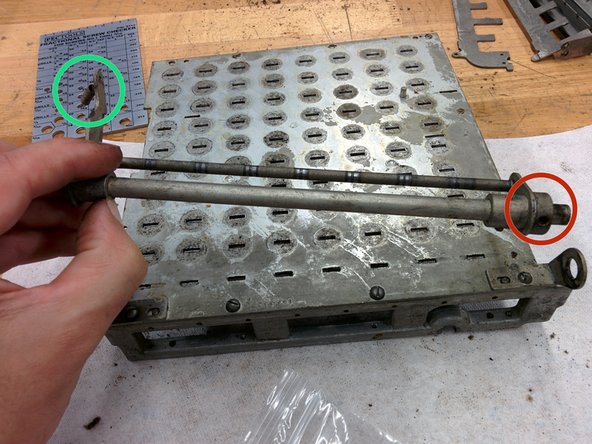
This shaft runs the length of the carriage. Push it out to the right. You'll probably have to pivot the carriage up and down to help it come out. Ninety years of exposure to air can't have been good for it.
-
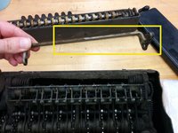
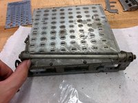
Now lift the carriage completely off.
-
This other part comes off with it.
-
-
-
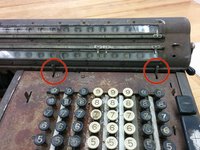
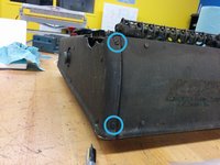
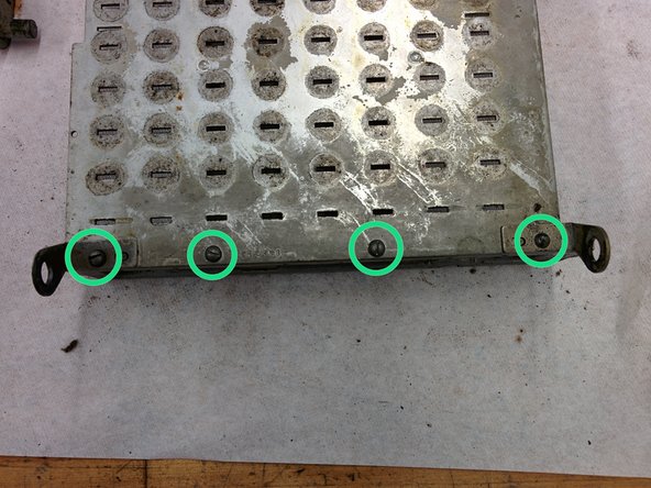
Remove these two screws. They are #6-40, about 3/8".
-
On the back, remove these two screws. They are also #6-40, but about 1/4".
-
On the front, remove these two screws. They are also #6-40, 1/4".
-
Bag all these screws in bag #1.
-
-
-
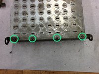
Remove these two screws. They are #6-40, 1/4".
-
They go into bag #1.
-
-
-
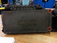
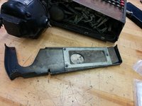
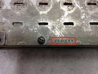
Scratched into the back panel you'll find the serial number. Mine is 143032. Write yours on every parts bag and on the box you're using to store the bigger parts.
-
-
-
In order to remove the front panel, you'll need to remove the carriage shift handle. However, this will likely have rusted in place.
-
Liberally apply lubricating penetrant to the screw, the hole on the opposite side, and the joining line.
-
-
-
Remove this one #6-40 3/8" screw. Put it in bag #1.
-
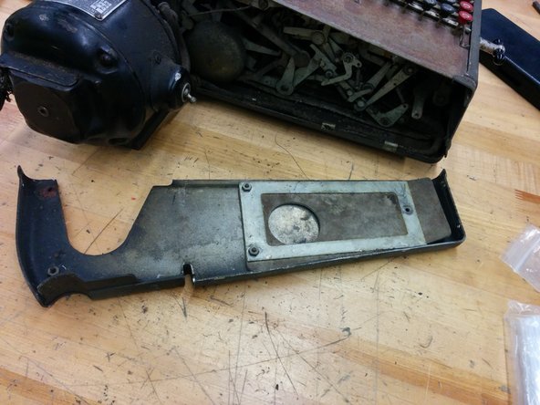
Lift upwards and off.
-
-
-
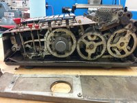
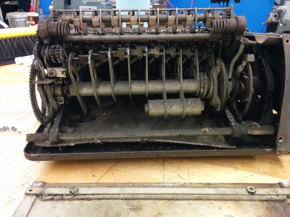
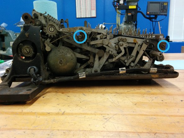
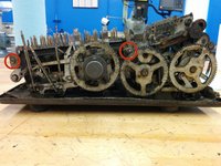
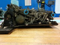
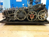
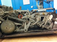
True story. When I was around eight years old, my dad brought home a surplus calculator like this one. I opened up this side first, and was confronted with this view of apparently infinite complexity.
-
I jiggled the controls a bit, tried to figure it out for about an hour, and when I couldn't make heads or tails of it, I took a hammer to the thing.
-
In part, this teardown is an apology for that moment of violence. It was the 70s. I'm sure disco must be partially to blame.
-
-
-
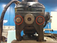
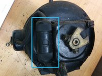
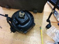
Tilt the calculator onto its right side so that the motor sticks straight up.
-
Remove these two bolts, placing them in bag 1.
-
Tilt the calculator back down.
-
Pull off the motor, and unplug the wire connecting it to the calculator.
-
Set it aside.
-
-
-
1x machine screw, #4-48, 1/4", miniature head (1/8" dia)
-
8x machine screw, #6-40, 1/4"
-
3x machine screw, #6-40, 3/8"
-
1x machine screw, #8-36, 5/16"
-
2x hex head bolt, 5/16-18, 7/8"
-
2x split lock washer, 5/16"
-
-
-
Start a new bag 2.
-
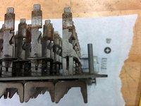
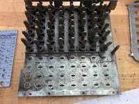
Pull straight up the 80 numeric keys, the zero key, the repeat and the nonrepeat keys. Most should come off by hand, but you will have to use pliers to pull up the stubborn ones. Put the jaws under the keys and lever them up. Use a rag to protect the calculator from the jaws.
-
Put all the keys in bag #2.
-
-
-
Remove the screws holding the add and subtract keys. They are #4-48, 3/16".
-
Pull the add and subtract keys off.
-
Place the add and subtract keys into bag 2.
-
Start a new bag 3 and put the screws in it.
-
-
-
80x numeric keys
-
1x zeroing key
-
1x repeat (R) key
-
1x nonrepeat (blank) key
-
1x add key
-
1x subtract key
-
-
-
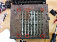
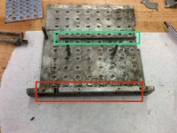
Remove the indicated six screws. They are #5-44, 1/4".
-
Place the screws in bag 3.
-
Lift off the whole assembly of decimal indicators and set them aside.
-
They appear to have been painted white on one side and green on the other. But who can tell under all that dirt.
-
-
-
Remove these other six screws. They are also #5-44, 1/4". Place the screws in bag 3.
-
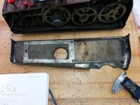
Lever up the top panel, pulling on one side, then the other, until the whole thing comes off. It will come off with the front panel.
-
Set the top/front panels aside.
-
It's impossible to tell from the rusty top, but the top was originally painted a dark green.
-
-
-
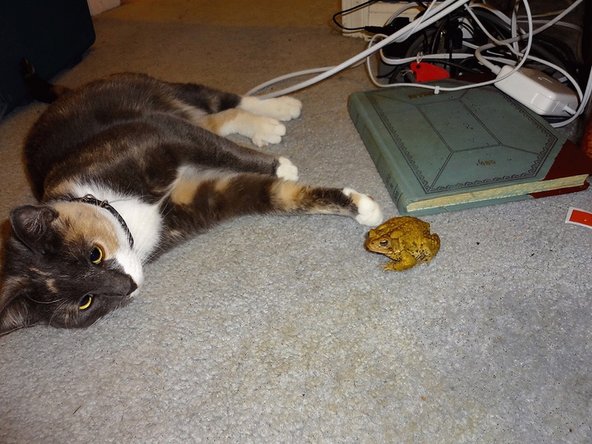
This would be a good time to go for a stretch.
-
Maybe make friends with a toad.
-
-
-
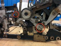
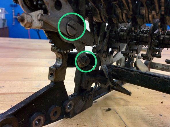
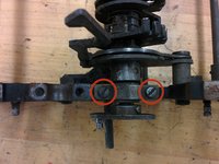
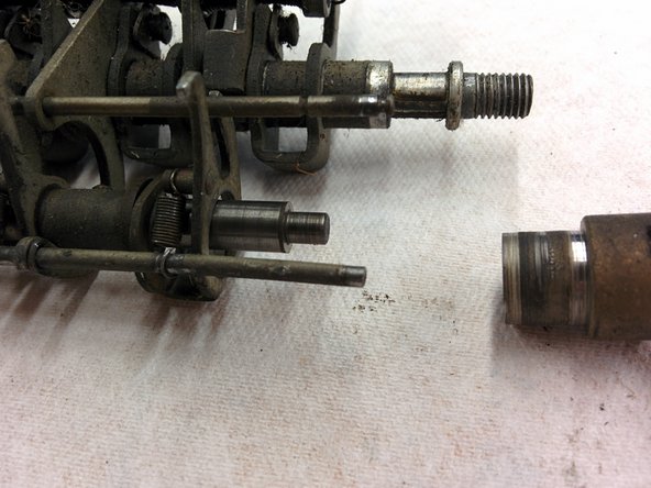
On the right side, remove this screw in the front (#8-36, 5/8"), and the screw that looks like a shaft in the middle.
-
That shaft-like screw is essentially a #8-36, 5/8" screw attached to a 1" head, 7/32" in diameter.
-
On the left side, remove this screw in the front (#8-36, 5/8") and the screw that looks like a shaft in the middle. This one is also #8-36, 5/8" but with a 1-1/2" x 7/32" head.
-
All these go into bag 3.
-
-
-
On the right side front, unscrew this #8-36, 1" screw and remove the washer.
-
Place them in bag 3.
-
Remove the switch and wire and set it aside.
-
On the left side front, remove the corresponding screw, #8-36, 5/8".
-
Put it in bag 3.
-
-
-
12x machine screw, #5-44, 1/4"
-
2x machine screw, #4-48, 3/16"
-
3x machine screw, #8-36, 5/8"
-
1x machine screw, #8-36, 1"
-
3x split lock washer, #8
-
1x flat washer, #8
-
(continued)
-
-
-
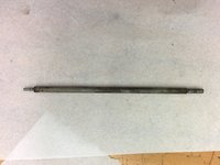
1x shaft with threaded end, 7/32" dia, 1 5/8" overall length, 1" travel length, #8-36
-
1x shaft with threaded end, 7/32" dia, 2 1/8" overall length, 1 17/32" travel length, #8-36
-
-
-
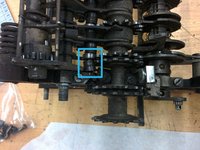
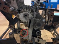
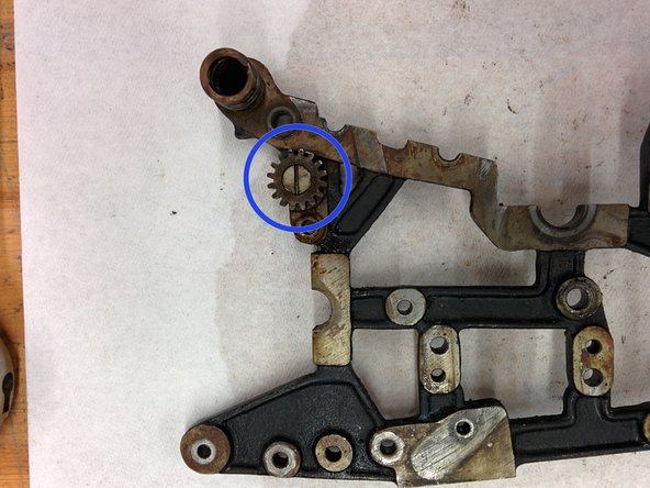
Start a new bag 4.
-
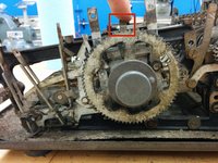
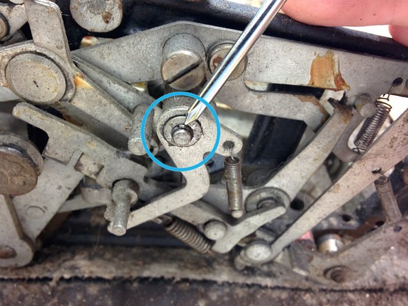
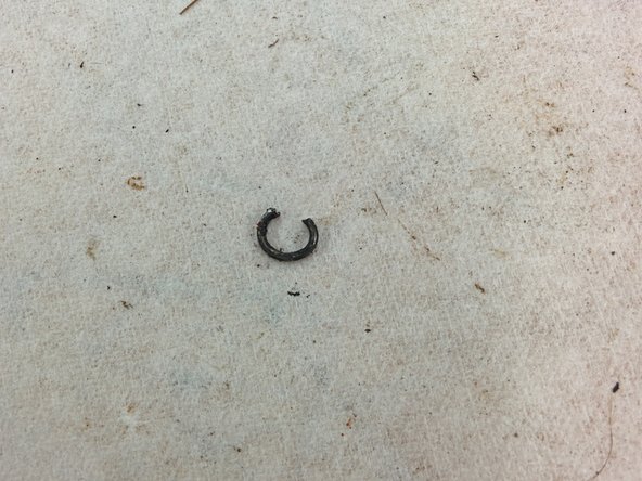
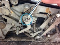
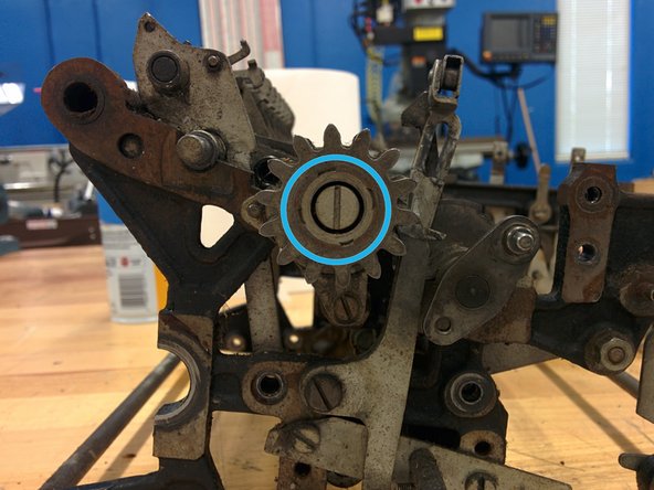
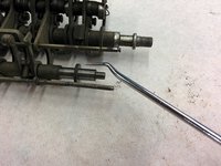
Remove the retaining clip. Rotate the clip so that the gap is facing up. Now hook your needlenose pliers into the ears and pull down slowly but firmly. Hopefully the clip will remain on the jaws of the pliers, but it may decide to escape. In that case, go find it.
-
Remove the washer.
-
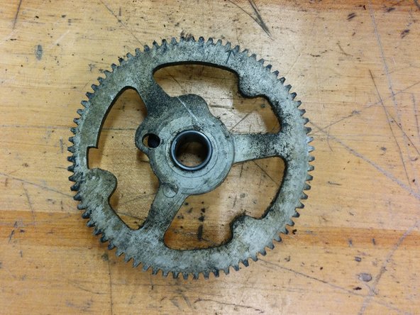
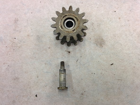
Remove the middle gear.
-
Place all these into bag 4.
-
-
-
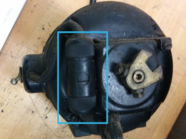
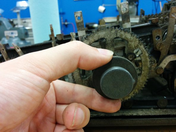
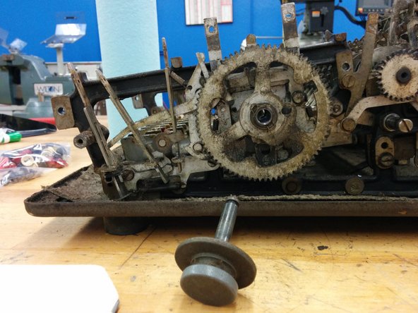
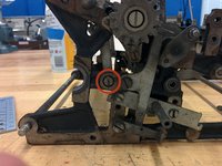
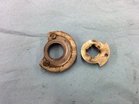
With your finger, pull the cover plug release lever towards the front of the calculator.
-
Still holding the lever, pull the cover plug off its shaft.
-
Place the cover plug in bag 4.
-
-
-
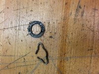
Gear, 77t, with two timing markers
-
Flat washer, 1/2" od, 5/16" id
-
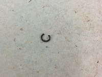
Retaining clip, 0.040" wire
-
Cover plug
-
-
-
Start a new bag 5.
-
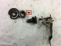
In the same way you removed the middle gear, remove the retaining clip and washer from the crank gear.
-
Place clip, washer, and gear in bag 5.
-
-
-
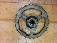
Gear, 77t, with one timing marker
-
Washer, 5/8" od, 7/16" id
-
Retaining clip, 0.040" wire
-
-
-
Start a new bag 6.
-
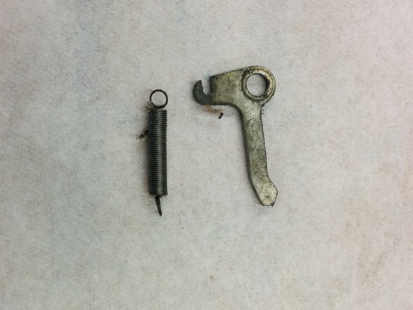
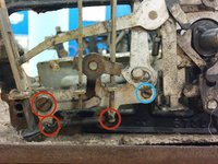
On the right side front of the machine, unhook the repeat/nonrepeat detent spring on both sides.
-
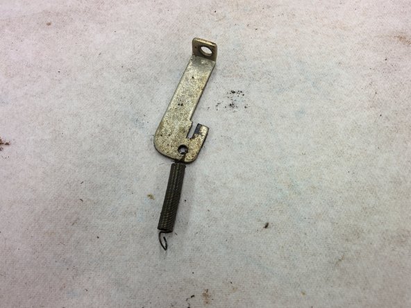
Unscrew this screw, #8-36, 5/16" with a 0.1" long, 7/32" diameter shoulder.
-
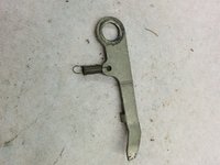
Remove the latch lever, and put it with spring and screw in bag 6.
-
Unscrew this screw, #8-36, 5/16" and put it in bag 6.
-
Pull off the zero/repeat/nonrepeat key assembly. Put it in bag 6.
-
-
-
1x machine screw, #8-36, 5/16"
-
1x machine screw, #8-36, 5/16" with 0.1", 7/32" diameter shoulder
-
1x expansion spring, 0.020" wire, 3/16" od, 13/16" length
-
Repeat/nonrepeat/zero assembly (2 parts)
-
Latch lever
-
-
-
Start a new bag 7.
-
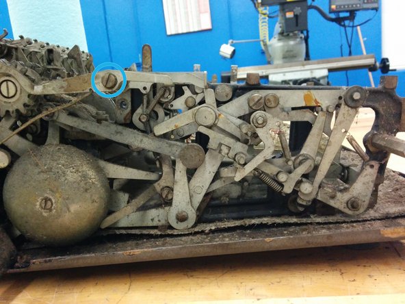
On the left side rear of the machine, unhook the top two springs from the indicated post.
-
Unscrew this screw. There is a nut on the other side of the frame, so be sure to catch it.
-
Remove the bell mechanism. Place all parts in bag 7.
-
-
-
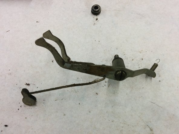
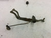
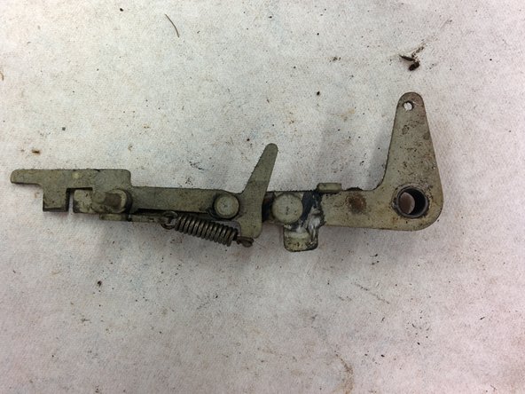
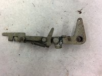
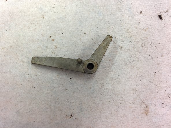
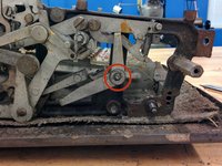
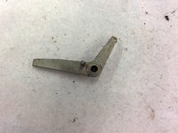
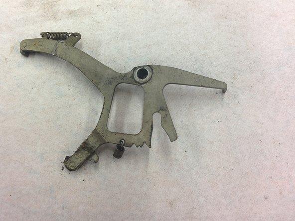
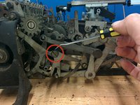
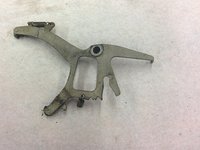
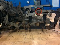
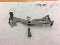
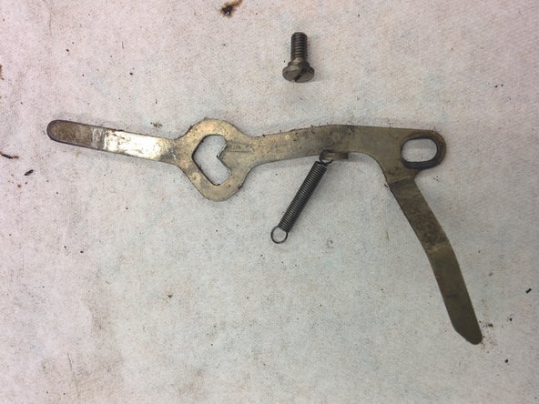
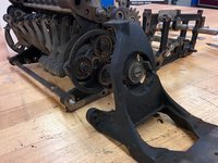
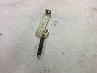
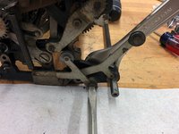
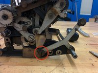
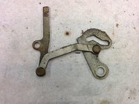
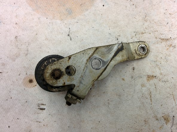
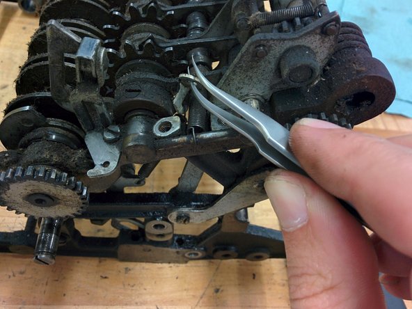
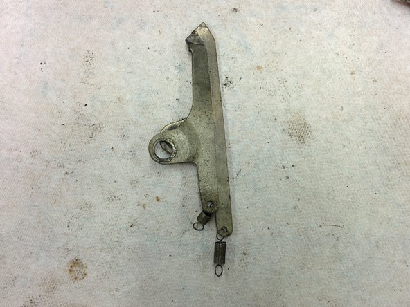
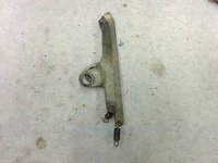
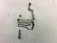
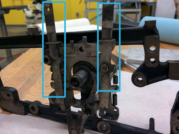
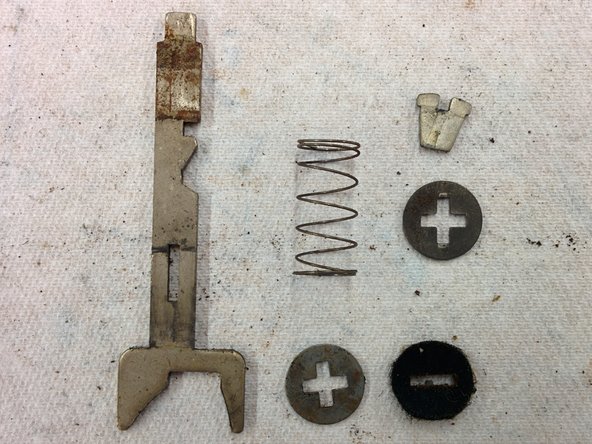
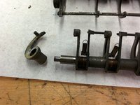
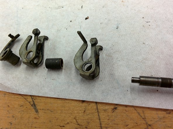
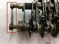
On the left side, we will be removing this lever.
-
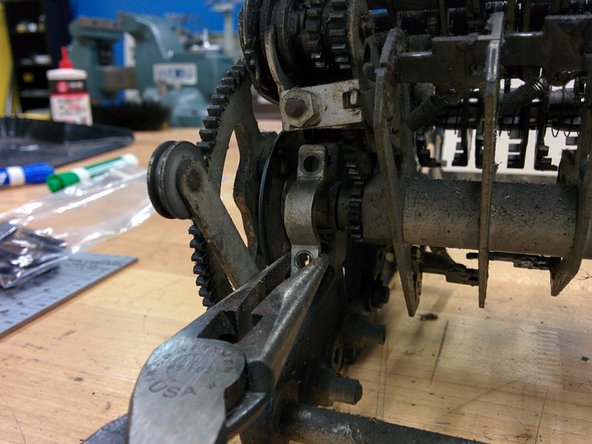
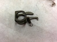
It is held on its shaft with a retaining clip and a washer. The clip is actually just what appears to be one loop of a thick spring. Find the gap in the wire, then use the dental pick and a very small screwdriver to pry apart the gap enough so that you can remove it with the needlenose pliers.
-
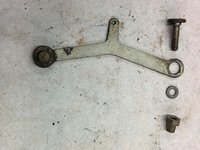
Remove the washer (5/16" outer diameter).
-
Also unhook the end of the spring from its post.
-
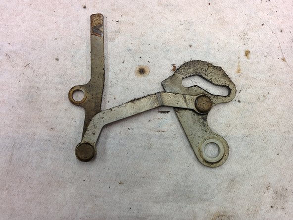
Place retaining clip, washer, and lever into bag 7.
-
-
-
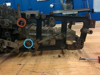
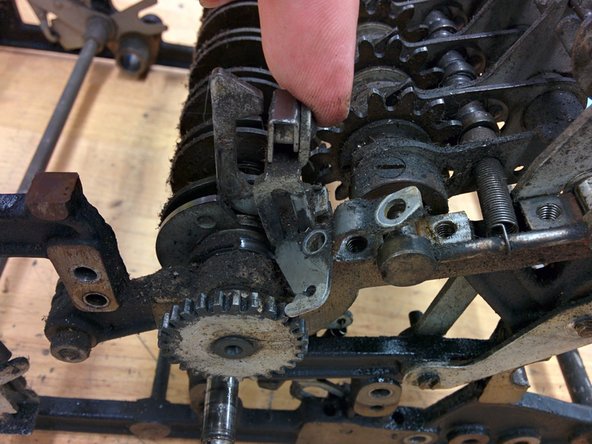
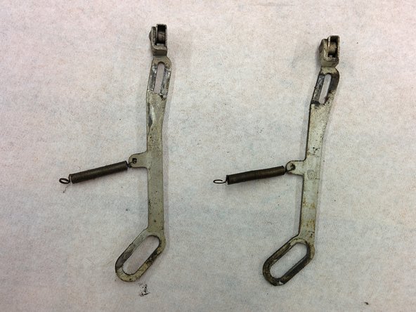
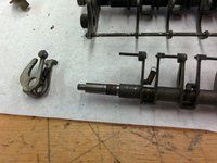
Unhook this spring at the indicated point.
-
As with the previous lever, remove the retaining wire and washer (1/2" outer diameter) along with the lever.
-
Put everything in bag 7.
-
-
-
Start a new bag 8.
-
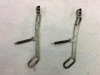
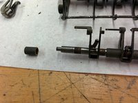
As before, remove retaining wire, washer, and lever. The washer is 5/16" o.d.
-
Put these parts in bag 8.
-
-
-
Again, remove retaining wire, washer (1/2" o.d.) and lever.
-
Place in bag 8.
-
-
-
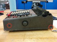
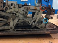
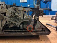
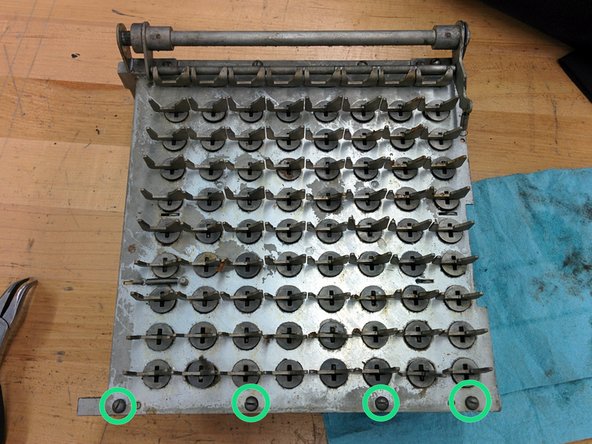
Tip the calculator onto its right side and unscrew four of the five feet from the bottom.
-
You may not have to use a screwdriver. I could just turn the feet and they unscrewed.
-
Place the feet in bag 8.
-
-
-
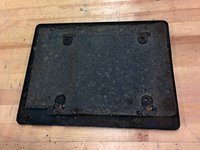
Just pull it right off and set it aside. The bottom mat may stick to the frame. Just pull on it until it comes off.
-
Flip the calculator so it is upside down.
-
-
-
Start a new bag 9.
-
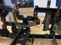
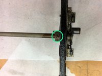
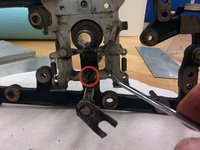
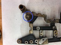
On the left side (which is now on the right, since you've flipped the thing over, but we'll still call it the left side) unscrew the set screw, #6-40, 3/16", from the collar.
-
I would unscrew it completely. Put it in bag 9.
-
Rotate the collar and move it down the shaft a bit. This is to loosen it. You probably won't have to use penetrating lubricant or lubricating penetrant.
-
-
-
Flip the calculator back right side up.
-
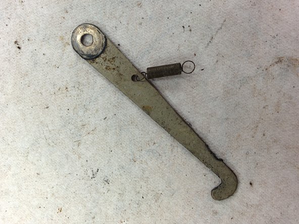
On the left side, remove this screw. It is 3/16-32, 1", 1/4" diameter shoulder. Put it in bag 9.
-
Remove the lever. You may have to maneuver it a bit to get it free. Put it in bag 9.
-
-
-
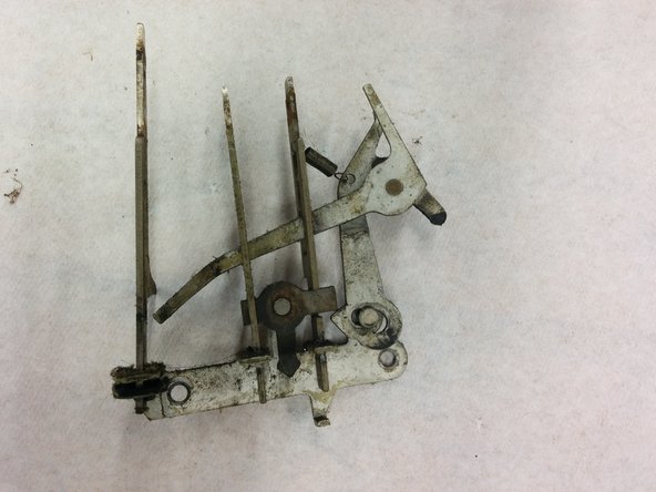
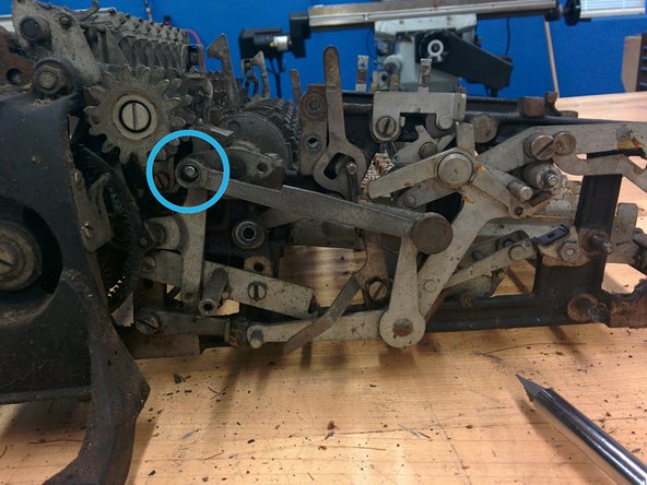
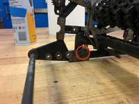
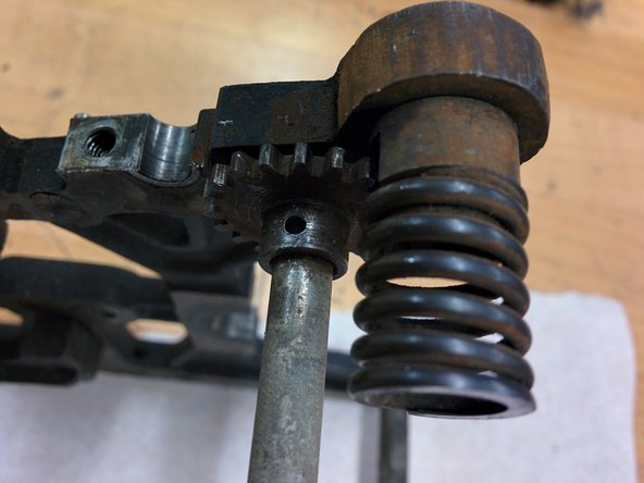
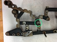
On the inside part of the left frame, unhook this end of the large spring.
-
Back on the outer side of the left frame, bend this cotter pin and pull it out of its hole. Put it in bag 9. Don't worry if it breaks, because it is easily replaced.
-
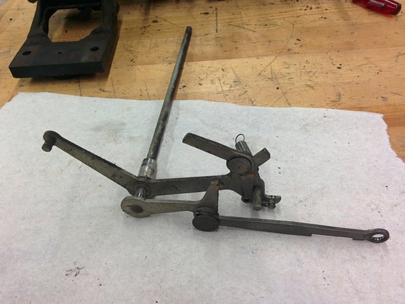
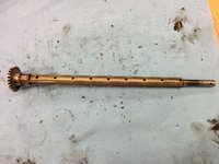
Pull the entire lever assembly with shaft straight out. Pull it smoothly along the direction of the shaft, possibly using another hand to push the shaft collar off the other end.
-
Put the collar in bag 9, and set the lever/shaft assembly aside.
-
-
-
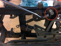
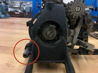
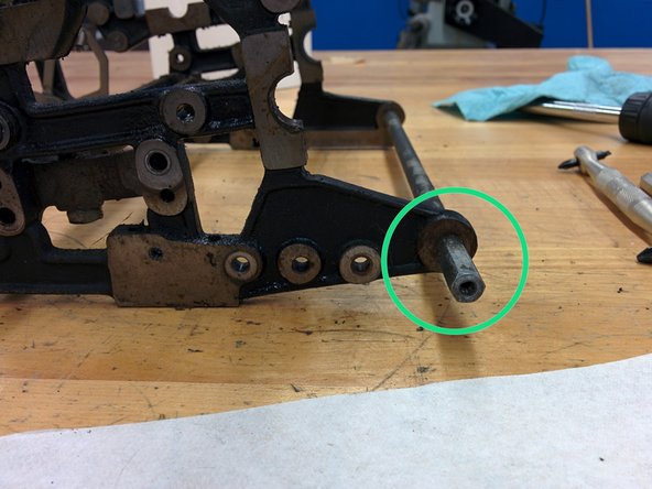
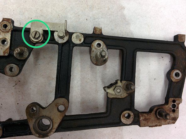
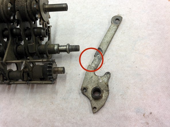
On the left side, remove this screw, #8-36, 3/4", 7/32" shoulder.
-
Remove the lever. Put all parts in bag 9.
-
-
-
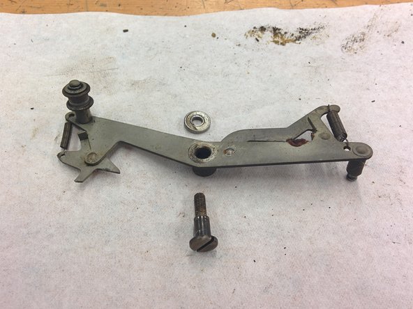
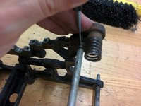
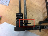
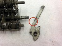
Unhook the spring from its post.
-
Remove the screw, #8-36, 3/8", 7/32" shoulder.
-
Remove lever and place it with screw in bag 9.
-
-
-
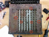
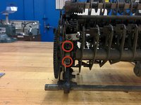
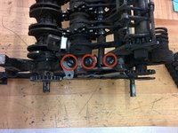
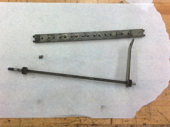
Remove these two screws, #4-48, 1/4" and put them in bag 9.
-
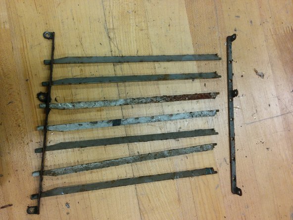
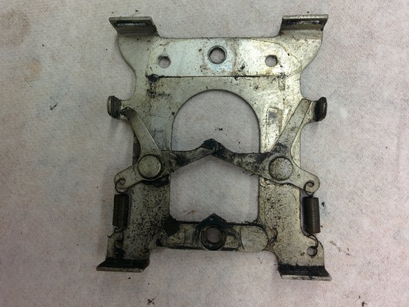
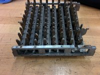
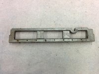
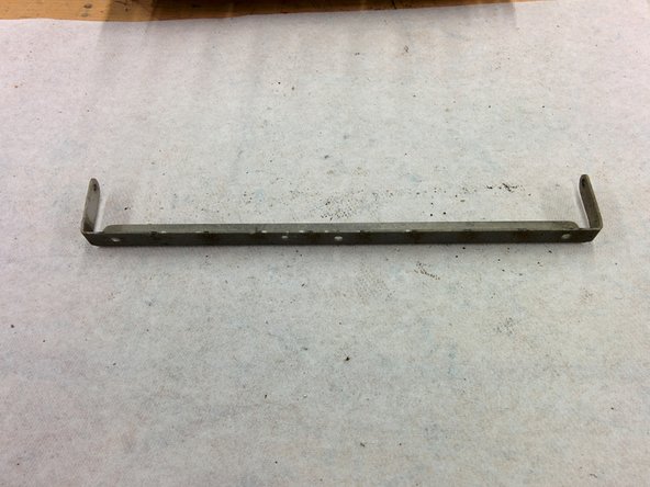
Remove the retaining bar.
-
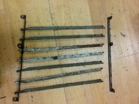
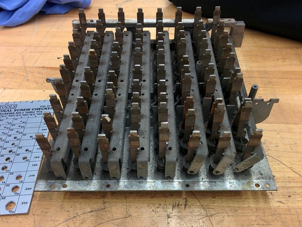
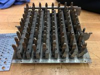
Get a few paper towels, because the rock bars will be very greasy.
-
Remove the rock bars, wrapping them in the paper towels. We can clean them later.
-
Also put the retaining bar in with them.
-
-
-
-
Start a new bag 10.
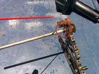
-
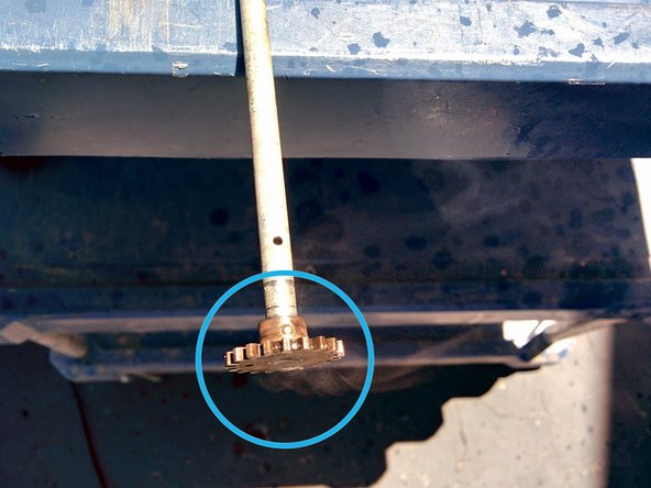
The oiling tube leads down to a hole in a collar.
-
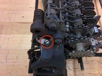
On the left side rear, remove this screw and put it in bag 10.
-
Put the oiling tube into bag 10.
-
Remove this 3/8" nut and put it into bag 10.
-
-
-
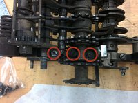
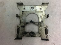
This could probably have been seen from the bottom if we had taken it off first.
-
The model number on this one is KA-163, which indicates a 16 digit accumulator and 3 registers (the accumulator plus two counters).
-
The rest is the serial number.
-
-
-
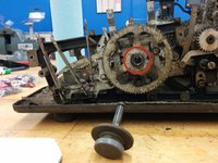
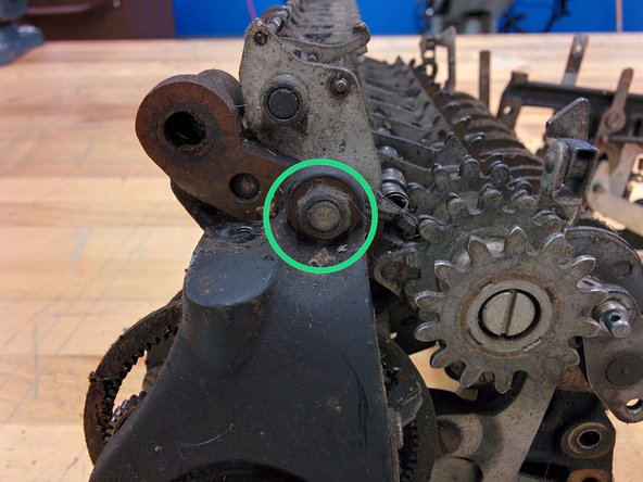
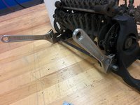
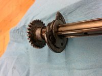
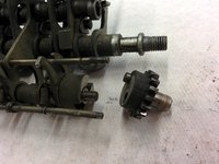
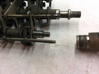
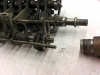
Unscrew the 3/8" hex standoff from the threaded shaft.
-
You may need to use wrenches to prevent the shaft from rotating, but probably not.
-
Place the standoff in bag 10.
-
-
-
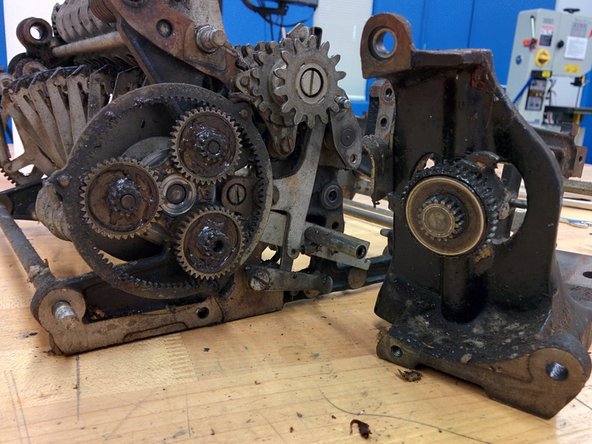
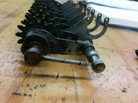
Pull the motor mount away from the frame. You may have to wiggle it and gently pry it off.
-
Set it aside.
-
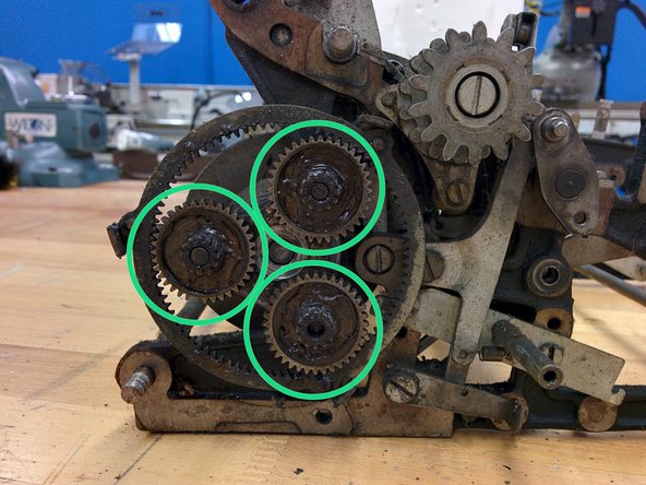
Remove the three 36t/12t gears by just sliding them out. Put them in bag 10.
-
-
-
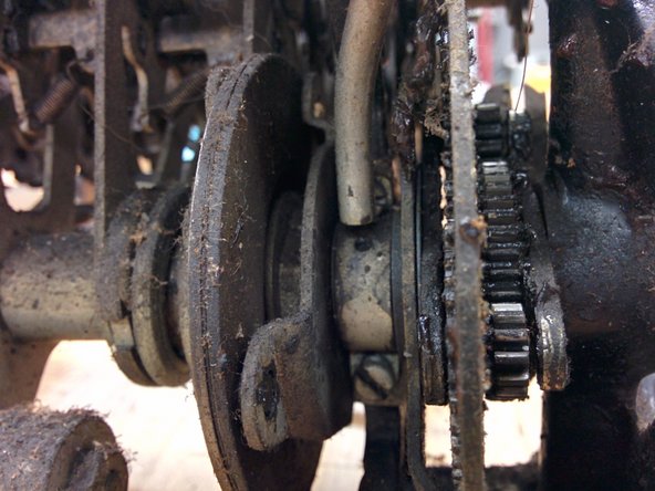
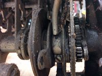
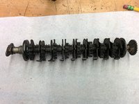
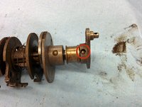
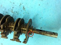
With just a little persuasion, pull off the entire carry/drive shaft assembly.
-
The motor drive gear should slide off.
-
Set these assemblies aside.
-
-
-
On the right side rear, remove this screw, 3/16-32, threaded length 1/2", and the spring at the indicated point. There is nut on the other side, so it will be helpful to use a wrench to hold the nut.
-
The screw on mine doesn't come off the lever. There is a large bushing between the lever and the frame which does not come off, either.
-
Place in bag 10.
-
-
-
Remove screw, 3/16-32, threaded length 13/32". As before, there is a nut on the other side.
-
There is also a washer, 3/8" od, 0.047" thickness, between the lever and the frame.
-
The screw has an eccentric shoulder on it.
-
Place all parts in bag 10.
-
-
-
Remove two screws, #8-36, 10/32" and 3/16-32, threaded length 7/16".
-
Remove lever assembly.
-
Place all parts in bag 10.
-
-
-
Start a new bag 11.
-
From right side rear, remove 5/16" hex nut, #6-40, 0.095" thick.
-
On the inside of the right side rear, remove 5/16" hex nut, 0.156 thick, and screw, #6-40, 1/4".
-
Remove the lever that the screw was holding in.
-
-
-
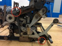
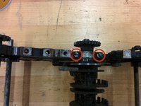
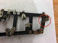
On the left rear, remove these three screws, #8-36, 5/16".
-
The screw on the right is difficult to get to. Use a long thin screwdriver to loosen the screw a tiny bit, then a smaller screwdriver to remove the screw.
-
The screw on the right holds down two parts.
-
The screw on the left has a hook for a spring which runs along the length of the machine. You will likely be able to remove a short segment of the larger surrounding spring. Hook the end of the interior spring around the bushing after removing the short outer spring segment.
-
-
-
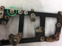
On the left side rear, remove this screw, #8-36.
-
Remove this screw, #8-36 with 1/4" shaft.
-
Slide the gear off. Note that this gear has a recess for the screw.
-
Slide another gear off the right side. This gear does not have a recess. Note: I might have gotten this gear from a few steps farther down, need to verify this.
-
-
-
Start a new bag 13.
-
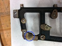
On the left rear side, remove this screw, 3/16-32, 7/16", holding two levers.
-
Unhook the lever springs. Note that the lever with the shorter arm and shorter spring goes in front.
-
There is also a washer between the screw head and the first lever, 9/32" od, 7/64" thick.
-
-
-
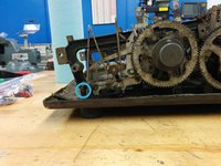
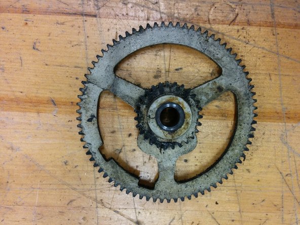
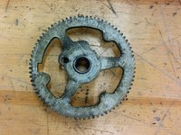
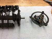
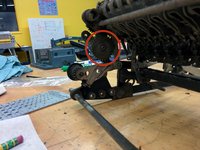
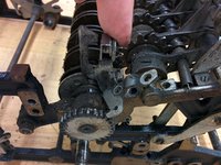
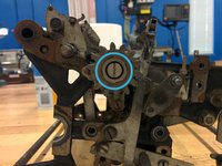
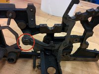
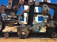
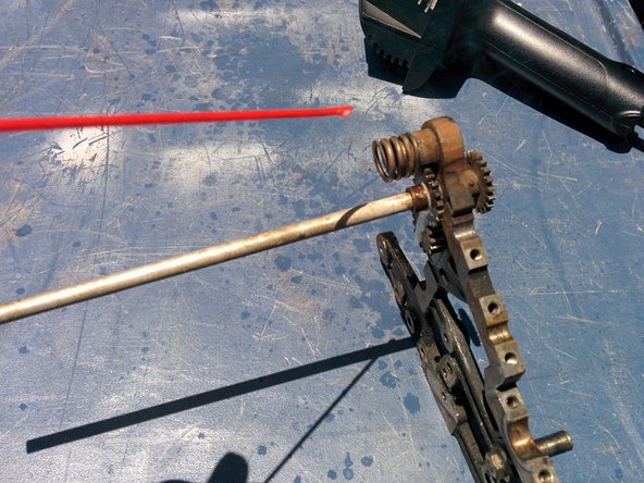
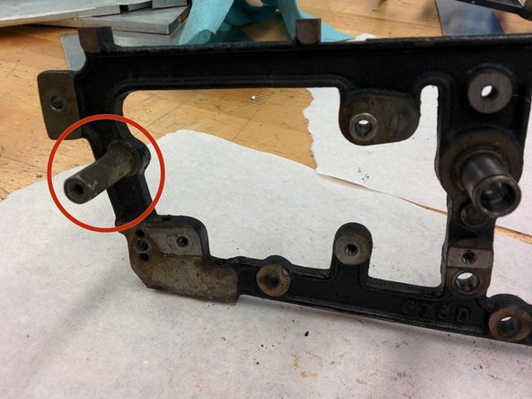
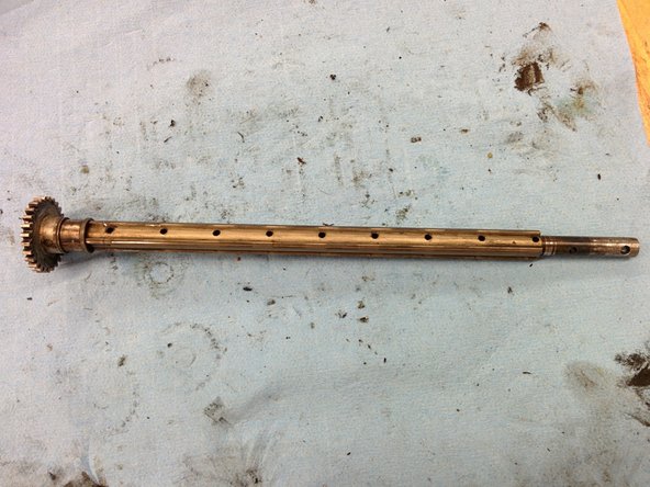
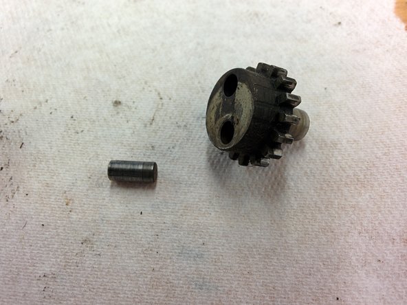
The only thing now preventing the two frames from being separated is this gear.
-
It is fixed to the shaft with a taper pin.
-
A taper pin is a pin that tapers from a wide end to a narrow end used to affix parts onto a shaft. The machinist would put the gear on the shaft, drill a hole, then taper the hole by using a tapering reamer. Then the machinist would put the taper pin in, give it a few gentle whacks with a hammer, and grind off any end sticking out too much.
-
-
-
Before you get started on removing the taper pins, you must go for a luxurious stretch.
-
-
-
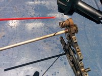
Take a heat gun and blow heat on the part for about two minutes to get it up to maximum temperature.
-
Spray the part with penetrating lubricant. It will smoke slightly, and it won't ignite.
-
If the lubricant evaporates, spray some more on, until the lubricant shows no sign of evaporating anymore, meaning that the temperature of the part has dropped significantly.
-
Repeat the heat - lubricant cycle three more times.
-
The idea is to break the bond between the taper pin and the part, and get some lubricant in the tiny microscopic gap in between.
-
-
-
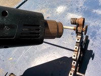
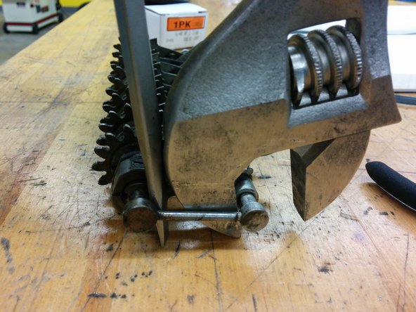
Take the part over to the arbor press.
-
You must support the part against something that will provide maximum surface area to the part, but also allow the taper pin to move at the bottom.
-
A piece of aluminum with a semicircular depression is perfect. You can do this either with a drill, then sawing off halfway through the diameter of the hole, or with an endmill of the right diameter.
-
Then cut a smaller notch the length of the depression to allow the pin to move. Again, this could be done with a drill and a saw, or an endmill.
-
-
-
With calipers, measure the width of each end of the pin. You want to find the smaller of the two ends. The smaller the pin, the more difficult this is.
-
On my machine, the smaller pins had one end ground flush to the part, and the other sticking out. The end that stuck out was the smaller end.
-
Many of the larger taper pins have a rounded end and a flat end. The rounded end is the larger end.
-
Position the part in the arbor press so that the part is supported by the jig you made, and the small end of the pin is up.
-
Press on the pin with the arbor press. If you are close to using all of your strength and the pin has still not moved, give it a few more heat - lubricant cycles.
-
If the thing still doesn't move, you may be pressing on the wrong end. In which case, see the next step.
-
-
-
If you tried to press the pin out, and it just won't come out, or maybe the pin is actually ground flush on both ends so there's nothing to press, then you will have to get a 1/16" end mill (not a drill) and drill out a bit of each end.
-
Give it a few cycles of heat - lubricant.
-
Then use a 1/16" flat pin punch and hammer at the pin. But don't use your full strength: that will just compress the pin and expand it, making it more stuck.
-
If that still doesn't work, you'll have to drill out the entire pin, which is unfortunate because now you will have to replace the pin when you assemble the machine.
-
-
-
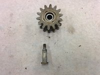
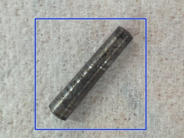
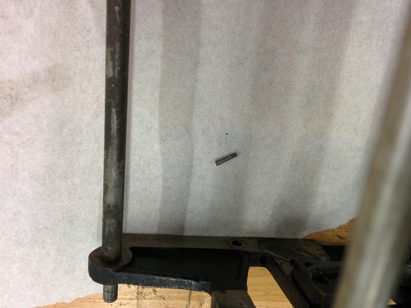
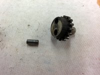
Start a new bag 16. Remove the taper pin from the gear on the upper left side.
-
Bag the taper pin. It should be about 0.086" on the wide end, 0.071" on the narrow end, and about 0.410" long. That is a taper of about 1/2" per 12", which is not a modern standard taper pin size -- 1/4" per 12" is the standard today.
-
However, If the wide end were 0.080" then we'd get a standard taper. Perhaps the wide end was widened a bit by the installation?
-
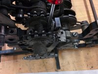
Now you can pull apart the frame. The gear will slide off its shaft. You may have to pry off the big iron piece in the middle, and move one side of the frame, then the other, but eventually the sides will separate.
-
You can pull of the rightmost rectangular part and the shaft second from the right. Set the rectangular part aside, and bag the spring.
-
-
-
On the right frame, unscrew this screw. There is a thin nut on the other side of the frame that you should try to hold steady or loosen slightly. If that doesn't work, just slowly turn the screw, since the nut will add lots and lots of friction.
-
Remove the spring from its post on the frame, and remove the lever.
-
The nut should now slide out.
-
-
-
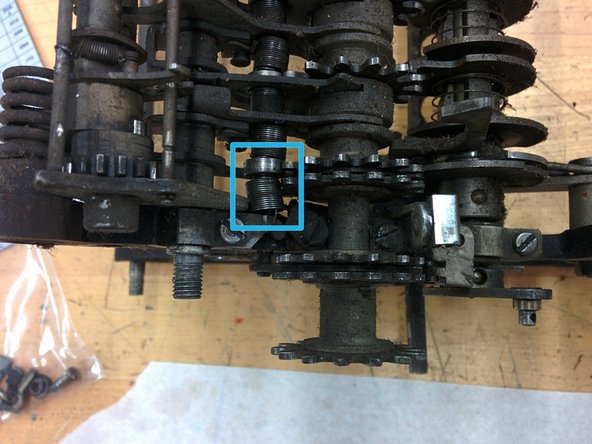
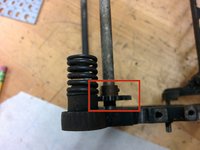
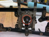
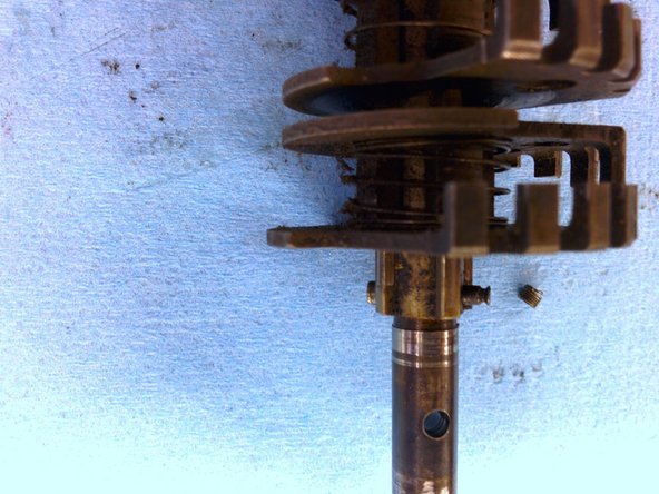
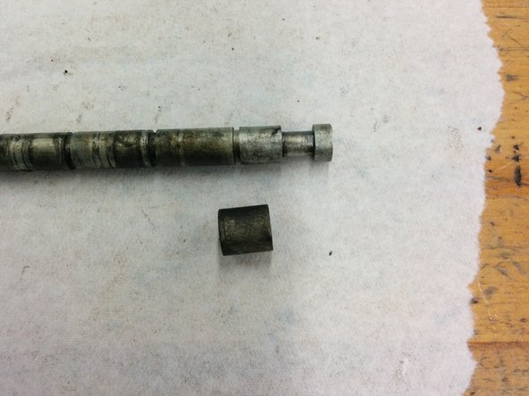
Loosen, but do not remove, this set screw. Slide the ring over a bit.
-
On the right frame, there is a cam ring that is loose. Remove it, if you haven't already.
-
You should now be able to jiggle these levers loose, Remove their springs first. You will probably have to slide the shaft a bit out, also.
-
-
-
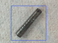
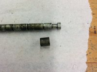
Remove taper pin and part from the right side of the shaft.
-
The taper pin is larger than the previous ones: 0.112" at the big end, 0.096" at the small end, and 0.517" long. This places the taper at nearly 3/8" per 12", which is not standard.
-
Again, though, if the wide end were 0.107", then the pin would be standard.
-
Slide the shaft out of the frame, and slide the bushing off the shaft.
-
-
-
Start a new bag 18.
-
On the front of the right frame, remove this 1" hex standoff with 3/16-32 threaded male end. There is also a washer, o.d. 0.379 x 0.048.
-
In the middle inside of the right frame, remove this 3/8 nut. There is a split washer on the inside and a regular washer on the outside, plus a screw-in post with 3/16-32 threads.
-
On the back of the right frame, unscrew the #8-36 screw holding the gear.
-
-
-
On the front of the left frame, unscrew the 1.5" hex standoff with 3/16-32 threaded male end. Remove its accompanying washer.
-
In the middle of the left frame, unscrew this #8-32 spring post, remove its accompanying washer and the part it was holding on.
-
In the front inside of the left frame, remove this 3/8 nut and the spring post 1/4-28 screw.
-
-
-
Now we are going to take apart the keyboard assembly! Hooray! Start five new bags: 19A through 19E.
-
Unhook the spring from the keyboard baseplate.
-
Turn the keyboard assembly so the clearing shaft is at the top, and remove these four #4-48 screws with their lock washers. Put them in bag 19E.
-
-
-
Turn the keyboard over and unhook both ends of this spring. Place the spring in bag 19E.
-
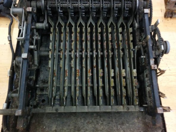
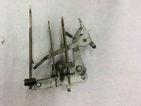
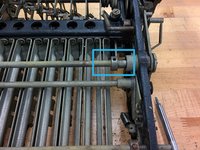
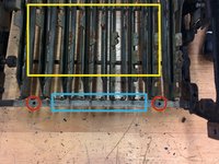
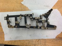
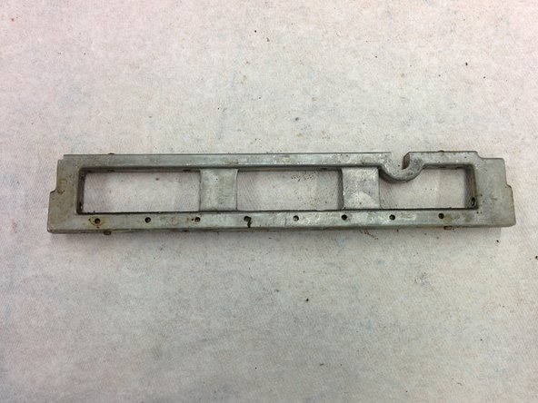
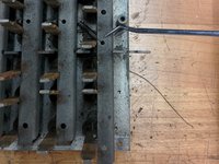
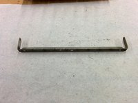
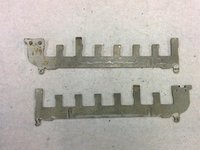
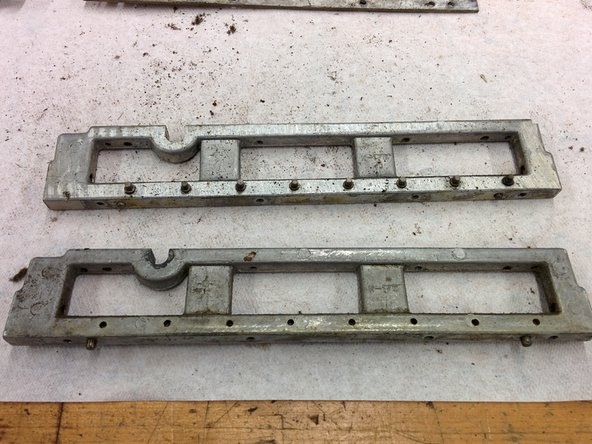
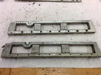
Turn the keyboard over again and remove these two horizontal clear and locking bars.
-
Note that the bars are identical except that one has an extra piece riveted to it. The riveted bar is farther up and points to the left. The other is lower down and points to the right, as shown in the image.
-
-
-
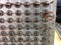
Next, lift the washer and spring off the top of the key stem.
-
You can now pull the key stem out from the bottom. There will be a metal washer and a felt washer.
-
Place the stems in bag 19A, the metal washers and retainers in 19B, the felt washers in 19C, and the key springs in 19D.
-
Do the same for all keys.
-
-
-
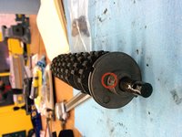
Start bag 20 and 20A. 20 will be for the parts, while 20A will be for the large separating springs that you'll see shortly.
-
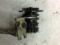
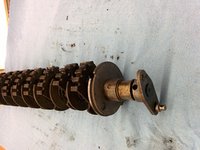
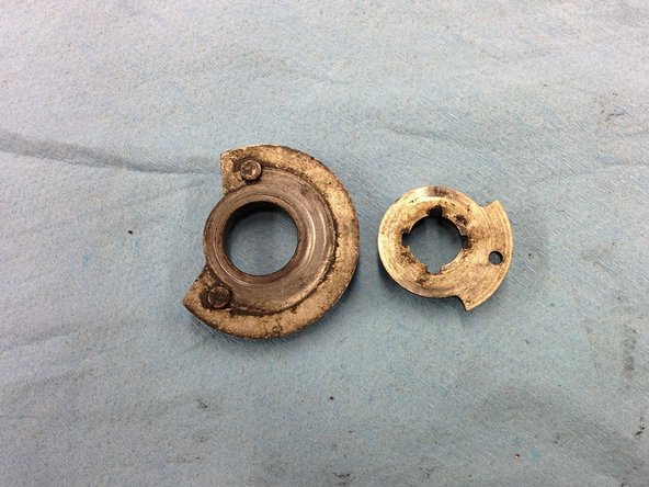
Remove this taper pin.
-
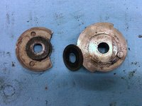
This will let you slide off two parts: the crank, and the bushing. Bag them with the taper pin.
-
-
-
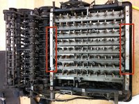
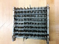
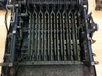
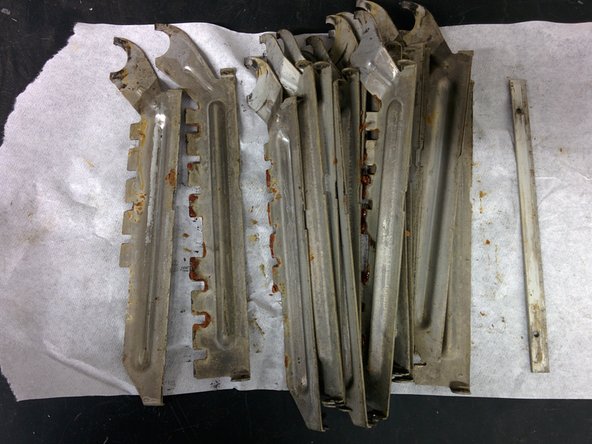
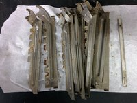
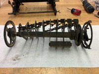
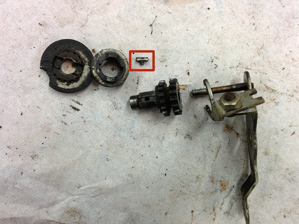
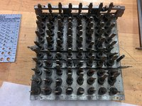
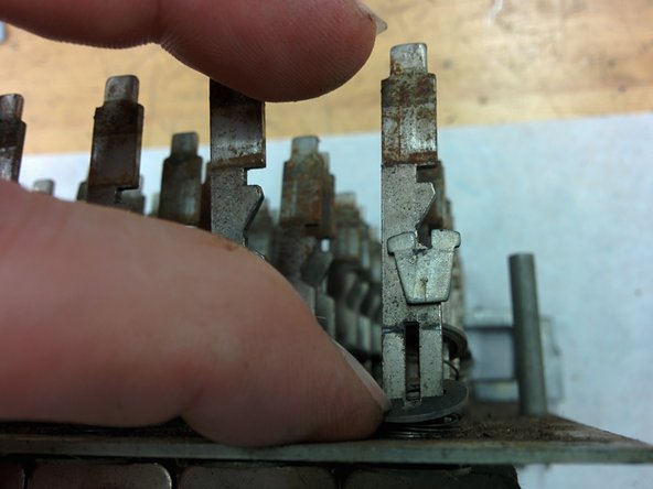
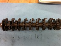
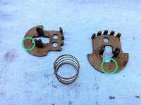
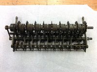
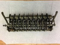
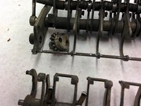
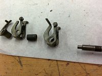
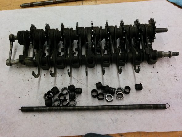
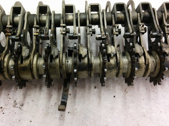
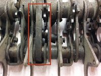
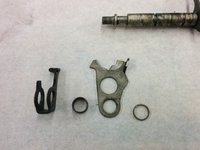
The selecting gears come in pairs of facing teeth with a spring in between each gear in the pair.
-
The gears have a stop pin between each pair which is held in place by some turns of a retaining spring.
-
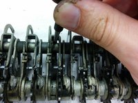
Use a very thin screwdriver (1mm worked for me) to pry out the end of the retaining spring. It should then slide off the pin.
-
You can now bag the retaining spring, the pin, the pair of gears, and their separating spring. Put the large separating spring in bag 20A.
-
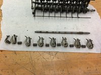
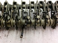
Each pair of gears is numbered. Write down the sequence! Mine is: 9, 10, 7, 6, 5, 4, 3, 2.
-
Remove all the gear pairs.
-
-
-
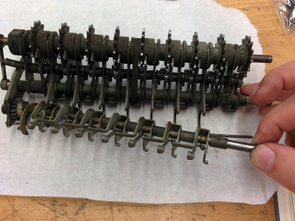
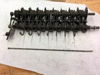
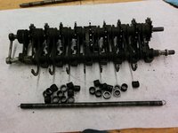
Start a new bag 21A and 21B. I put the small parts in 21B.
-
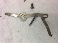
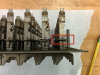
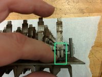
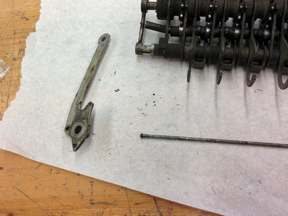
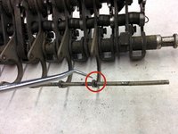
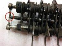
With the assembly face-up so that the side levers are facing downwards, remove this retaining wire.
-
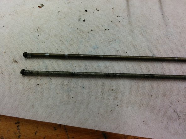
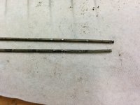
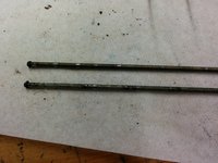
I'm not certain if the rod below this one also had a retaining wire, or if it just broke off. I did notice that the two rods are actually different.
-


3 commentaires
Whoa! Will you put it back together also?
Well, eventually. I'm concentrating my time on restoring a model K (manual version of this) here: https://www.youtube.com/watch?v=rRYE1x-4...
and a model F, here: https://www.youtube.com/watch?v=B1Y3gbEe....
I am a retired Monroe employee.
I would reassemble that K model ASAP, as you will forget how it goes back together.
I hope you marked all of the parts so you know exactly where they came from.
The key bails which engage the selection gears MUST go back into the same positions that they were in. They are formed and adjusted to each segment gear. they can be switched if you are lucky. After 90 years I KNOW that they have been reformed by a tech. I have reformed many of them myself.
You have made many other errors too.
Be very careful with the number wheels (or dials) as the will wash off if you clean them with anything other than warm water. Otherwise all the numbers will come off.
From personal experience.
Jim jimjjnn41@yahoo.com
Beautiful Tortie!
Ell Asces - Réponse