
Canon PowerShot G16 Motherboard Replacement

Introduction
Passez à l'étape 1This guide will show you how to replace the motherboard in your Canon PowerShot G16 which may be necessary if the motherboard has stopped working. A broken motherboard may result in a camera that doesn't turn on, frozen menus, or general unresponsiveness.
Ce dont vous avez besoin


-
-
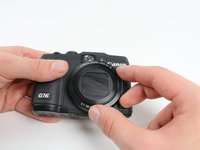
Open the battery flap on the bottom of the camera by applying pressure and pushing in the direction of the arrow.
-
Remove your finger and allow the flap to pop open.
-
-
-
Push the brown lever so that it pivots counterclockwise.
-
Grip and remove the battery.
-
-
-
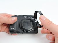
Remove the ring around the lens by simultaneously pressing the black button located at the bottom right of the ring and rotating the ring counterclockwise.
-
-
Outil utilisé dans cette étape :Tweezers$4.99
-
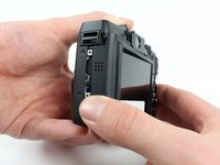
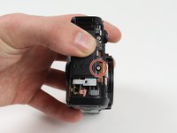
Reorient the camera so that you are looking at the back.
-
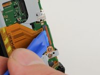
Unplug the button circuit board from the motherboard by unlocking the ZIF connector (gently lift the brown lock that keeps the cable in place).
-
Pull the connector downwards with the tweezers.
This is not completely correct. In order to pull the connector down without force, the little grey tap on the top of the connectorbox has to be flipped up.
This particular step cost me the connection to the button curcuit board. I would be grateful for an indication of where I can buy a replacement. Thanks.
You saved my connection. Thank you. iFixit... I'm somewhat disappointed these steps haven't been corrected.
It's worth noting that I had no luck with tweezers when attempting to remove the ribbon cable. The correct procedure would be to carefully lift the plastic clip with an iFixit spudger and then continue to step 12. The ribbon cable will pull out gently without any other coercion.
The clip is a red/terracotta colour, this should be lifted like a lid (the hinge is mounted in the grey housing). The connector should be pulled downward as described. This should definitely be corrected. Thanks for the comments to assist. I added this for extra clarity on the colours only.
-
-
-
-
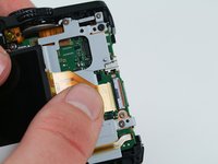
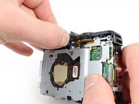
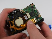
Unlock the ZIF connector for the large connector ribbon by lifting up on the brown flap with the plastic opening tool.
-
Gently pull the connector straight out of the housing with your fingers.
-
-
-
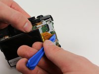
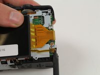
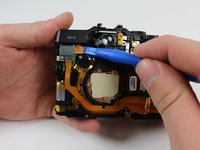
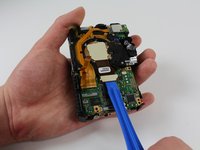
Unplug the small connector ribbon by pulling the cable outwards from the camera using a spudger or your fingers.
Be careful with this step. I broke the black connector off the motherboard for the small ribbon cable. It is very fragile. You might want to push down on the black connector to hold it in place while gently pulling the ribbon to the right to extract it from the connector. Don’t let the black connect pull up or twist.
-
-
-
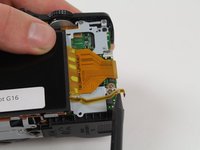
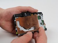
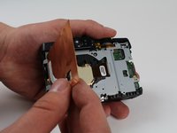
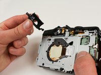
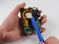
Lift and remove the copper EMI shield.
-
-
-
Reorient the camera so that you are looking at the back.
-
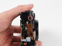
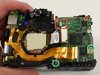
Remove the 6.8 mm screw to the left of the rear viewfinder using a Phillips #00 screwdriver.
-
Remove the 5.2 mm screw to the right of the rear viewfinder using a Phillips #00 screwdriver.
Somewhere between this step, and Step 21 the screw in the top right (right and up slightly of the orange circled 5.2mm screw) is removed. Suggest doing it here! Same with the one immediately to the right of that.
-
-
-
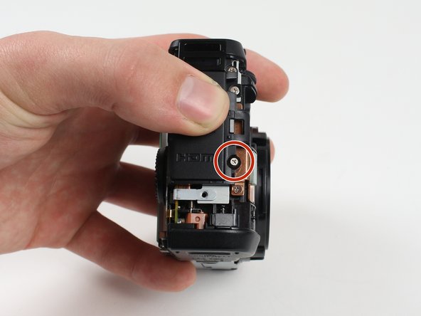
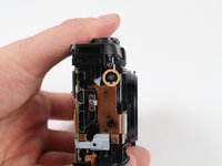
Remove the top 2.3 mm screw from the side with the ports using a Phillips #00 screwdriver.
-
Remove the 4 mm screw right below the one you just removed using a Phillips #00 screwdriver.
-
-
-
Remove the newly uncovered 2.8 mm screw from the right of the viewfinder using a Phillips #00 screwdriver.
-
Remove the 4.9 mm screw from top right of the metal casing on the back using a Phillips #00 screwdriver.
-
Remove the 4.3 mm screw from bottom right of the metal casing on the back using a Phillips #00 screwdriver.
-
Remove the newly uncovered screws from the right of the viewfinder using a Phillips #00 screwdriver. (Note, they're already removed on the picture)
The right-most screw encircled in green requires a smaller driver than the rest of the screws in this step.
-
-
-
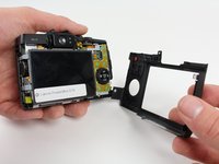
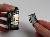
Remove the top portion of the casing by firmly grasping it and pulling it upward to lift it off.
At this point the tiny little ribbon cable and flat-flex with two diodes on it (face sensor?) may still be attached to the right of the viewfinder lens. It may just be caught on the two locating pegs. Pull it gently upwards before removing the top.
-
-
-
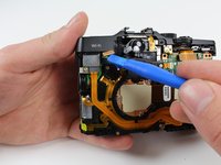
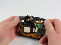
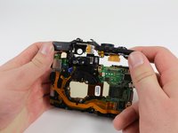
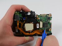
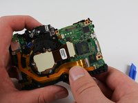
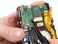
Lift the motherboard out of the camera.
It's missing the step to remove two screw that fixes the motherboard
Probably would be helpful to remove the memory card before doing this step. I’m not sure that was suggested previously.
Also, just opening the battery compartment door may be helpful in removing the main board.
-


To reassemble your device, follow these instructions in reverse order.
To reassemble your device, follow these instructions in reverse order.
Annulation : je n'ai pas terminé ce tutoriel.
2 autres ont terminé cette réparation.

Équipe

Cal Poly, Team 70-6, Forte Winter 2016 Membre de l'équipe Cal Poly, Team 70-6, Forte Winter 2016
CPSU-FORTE-W16S70G6
4 membres
7 tutoriels rédigés
3 commentaires
FYI, new main boards from Canon arrive without firmware installed. I can find no help in how to initialize a new main PCB from Canon. Anyone have links or advise?
Hello!
I broke a zif connector at a step 11.
Anybody have a part number for it?
Please help!
I have G15, but its not working. Anybody knows, what can be the problem?