
GeneralAire GA50A20 APS and PCB Replacement
Introduction
Passez à l'étape 1After what I suspect was a power surge a while back, my nice $450 electrostatic air cleaner became non-functioning, I was determine to find out why. I have to give GeneralAire credit, they actually have a usable troubleshooting section of their manual to help isolate functions and problems, and a part list to identify things, unfortunately the parts that needed replacement were more than an entire new unit… so I dug in a little deeper.
-
-
The first was to test the front panel LED indicator to rule out stupidity, but I had a good idea it went well beyond an indicator light as the filter had not been getting dirty.
-
This was a simple test, touch a 9V battery in the correct polarity to the red and black wires coming off the HV board, the indicator should light up brightly, and it did.
-
-
-
Making sure the yellow and blue wires from the 24VAC transformer are off the HV board, clip on a volt meter and energize the unit with the front panel switch. I should have seen voltage there for about 5 seconds as the air proving switch turned on then off, but got nothing.
-
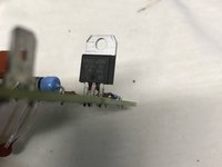
Per the manual, I moved back to the air proving switch, a small board with a PTC thermistor and a triac that energize to provide 120VAC to transformer. With output lead 4 disconnected, connect he volt meter between pin 1 and 4.
-
Energize the unit once again. Still only a few 100mV. Carefully check that there is 120VAC on the incoming posts 2 & 3, yep it's there.
-
-
-
-
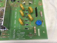
At this point, I had three suspects, the transformer, the air proving switch, and after closer inspection, I saw a brown discoloration on one of the high voltage capacitors.
-
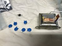
I decided to start with the transformer. After removing it from the unit, I checked the secondary and measured about 7 Ohm, reasonable. The primary was open, just to make sure I slowly opened the primary coil and after getting back to the winding, didn't see anything obvious, but it was still measuring open.
-
On removing the air proving switch, the thermistor checked out at about 1kOhms and responded with a squirt of canned air. All the discretes checked out except for the triac.
-
-
-
At this point I needed:
-
Air Proving Switch $76.38
-
Transformer $54.30
-
Power Control Board $310.27
-
New unit: $461.99
-
-
-
Looking up the individual parts:
-
Triac TO220AB $1.22
-
50VA transformer $22.70
-
2000pF cap, 6kV $0.77 each
-
Total parts plus some spares and a thermistor $38.60
-
Looks like I'm fixing this thing.
-
-
-
Just some careful desoldering with wick and wiggles.
-
All the old parts laid out.
-
-
-
Reverse the order of testing:
-
Connect the air proving switch and verify voltage at pins 1 & 4.
-
Connect the transformer and verify 24VAC out when energized and the air proving switch is cold.
-
With everything connected, powered up the unit and watched the indicator come on and go off. I turned on the fan to the air unit and the indicator came back on and very carefully bringing the voltage probe near the HV lines, I got some nice chirping.
-


To reassemble your device, follow these instructions in reverse order.
To reassemble your device, follow these instructions in reverse order.
2 commentaires
This post saved me hundreds of dollars! Mine had a blown transformer, transistor, and capacitors. My performance indicator light comes on now! I'm not sure how well it's working as I don't hear any popping sounds when I tap the ductwork. I also can't measure the high voltage. I don't want to buy a probe for one use.
Thanks so much for posting this!
Bill Brazell
D1-055D Rev2L12 June262013. According to the owner's manual dc voltage can be up to 8KV. Capacitors with a higher voltage are seemingly warranted. My board has a burned/cracked blue capacitor. The FV5M-10 HV diodes are rated at 10KV. Do you know the value of R10? I can't decipher code which on my newer PCB is 9210D 275. I could not measure the resistance with my DVM's highest scale of 10MegOhms. D1-D6 seem to have a very high forward resistance too (above 10Meg). My board has an ST LM-317T regulator instead of a Triac. As I studied my unit, I thought a simple inline AC Fuse could have save this from any damage or fire. Don