
iBook G4 14" 1.42 GHz Logic Board Replacement

Introduction
Passez à l'étape 1The motherboard includes all ports except the DC-In board.
Ce dont vous avez besoin
Pièces
Outils


Afficher plus…
-
-
Use a coin to rotate the battery locking screw 90 degrees clockwise.
-
Lift the battery out of the computer.
-
-
-
Pull the keyboard release tabs (shown in yellow) toward you and lift up on the keyboard until it pops free.
-
If the keyboard does not come free, use a small flathead screwdriver to turn the keyboard locking screw (shown in orange) 180 degrees in either direction and try again.
-
Flip the keyboard over, away from the screen, and rest it face-down on the trackpad area.
-
-
-
Push in the thin rims of the lower case surrounding the battery compartment, bending them past the tabs, and then lift up to free that corner of the lower case.
This part scared me, never in an iFixIt guide have I seen a warning like "trying times are ahead".
I used a plastic iPod opening tool and ran it around the seam in the same order pictured. I had the plastic off in less than a minute with almost no fuss.
-
-
-
Turn the computer so that the back is facing you and pull the lower case up and toward you until the back tabs pop free.
Citation de Paulix :
I found it easier and "safer" to use a spudge at the back as well (two on each side of the hinge)
I did too. Thanks, Paulix.
-
-
-
-
Remove the following 10 screws from the bottom shield:
-
Six 3 mm Phillips
-
Three 7.5 mm Phillips
-
One 14 mm Phillips
-
-
-
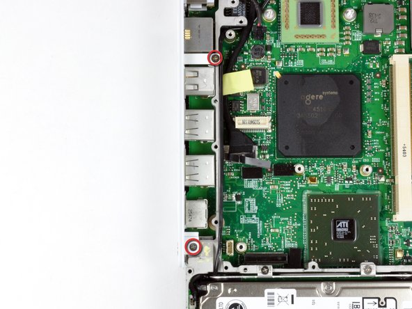
Remove the single Phillips screw securing the DC-In board.
You might not need to remove the entire DC-In board and cable. This is removed because the DC-In jack blocks the upper case from being lifted off. I just removed the screw and pushed the board slightly in when removing the upper case to provide clearance. You may want to tape the board loosely in place when the screw is out to prevent it from falling out.
-
-
-
Angle the DC-In board out of its compartment.
Citation de beefybov :
You need to undo the adhesive halfway down the cable, so you can lift the DC board to angle it out correctly. beefybov
Good call, beefybov.
-
-
-
Remove the following 11 screws from the bottom of the computer:
-
Three 3 mm Phillips around the battery compartment.
-
Three 4.5 mm Phillips along the optical drive bezel. (a magnetic screwdriver may help to lift these screws out)
-
One 12 mm Phillips in the lower right corner.
-
Four 14.5 mm Phillips.
-
-
-
Turn over the computer and open it.
-
Remove the 3 Phillips screws from the edges of the keyboard area.
A soft cloth like the one you use to clean your screen with. Not a towel because of the static that might be built up in heavier fabrics.
The picture has the lower *right* screw marked as "L" -- but that's a mistake; the short screw is, as described, on the lower LEFT side.
On my computer, the screw in lower right marked "L" (long?) in the picture is M3x6mm and the other two are M3x3mm.
Yes, the LONG screw goes into the bottom RIGHT corner if the screen is facing you as it does when you're using the computer.
-
-
-
Lift the upper case enough to disconnect the blue and white power cable from the logic board. Using your fingernails, carefully pry the connector from its socket.
-
Carefully disconnect the multicolored speaker cable from the logic board in the same fashion.
This is a very tough one. I did break both the power cable and speaker cable off the motherboard, and was unable to separate the motherboard-side connectors from the cable-side connectors even after that. Fortunately, this iBook was already bricked.
-
-
-
Remove the following 16 screws:
-
Thirteen 3 mm Phillips.
-
One 3 mm Phillips.
-
Two 4 mm Phillips.
Ditto
The little tabs on the shield that are intended to contact the metal on the ports and the optical drive had been flattened out on my iBook and were no longer in contact. I didn't notice this until I had installed the shield. Make sure the tabs are bent down a bit as to contact the ports and optical drive. This system looks like it replaced the foil tape on earlier models. Just my own observation.
-
-
-
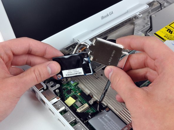
Remove the two Phillips screws at the corners of the modem.
-
Remove the two Phillips screws at the corners of the modem.
-
-
-
Remove the three 3 mm Phillips screws securing the AirPort card bracket to the metal framework.
-
Lift the AirPort card retaining bracket up and out of the computer.
-
-
-
Remove the following 9 screws and 2 nuts from the heat sink:
-
Four 3 mm Phillips from around the fan and the heat sink bracket. The bracket can also be removed at this point.
-
One 11.5 mm (left) and one 4.5 mm (right) Phillips from the plastic fingers of the hinge grill.
-
One 4.5 mm Phillips at the top right corner of the heat sink.
-
Two 6 mm Phillips on the lower left corner and face of the heat sink.
-
Two 4 mm screw nuts with attached springs from either side of the heat sink.
-
-
-
If necessary, use a spudger to pry up the heat sink from the left side near the hard drive.
-
While lifting straight up on the hinge grill with your right hand, lift the heat sink with your left hand from the end nearest the hard drive and remove the heat sink assembly from the computer.
-
-
-
Remove the two Phillips screws securing the white plastic fingers of the I/O bezel to the metal framework.
-
-
-
Remove the following 8 screws:
-
Eight 3.5 mm Phillips.
-
Two 3.5 mm Phillips near the sleep light connector.
-
One 3.5 mm Phillips with a large head in the lower left corner.
-
One 4.5 mm Phillips.
-
From top to bottom, disconnect the inverter, fan, and sleep light cables from the logic board.
-


To reassemble your device, follow these instructions in reverse order.
To reassemble your device, follow these instructions in reverse order.
Annulation : je n'ai pas terminé ce tutoriel.
20 autres ont terminé cette réparation.
