Traduction de l’étape 1
Étape 1


Remove the top plate screws
-
Remove the 6mm (BC) screw with a T6 Torx bit from the right side by the screen hinge.
-
Rotate the laptop so the screen hinge is at the rear. Remove the 16mm (BK) screw using a T6 Torx bit.
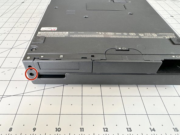
| [title] Remove the top plate screws | |
| - | [* red] Remove the 5mm screw with a T6 Torx bit from the right side by the screen hinge. |
| - | [* orange] Rotate the laptop so the screen hinge is at the rear. Remove the 16mm screw using a T6 Torx bit. |
| + | [* icon_note] This guide will use the [link|https://github.com/hrushka/701c.org/blob/main/assets/archive/IBM_ThinkPad_701_HMM.pdf|IBM Service Manual|new_window=true] ***two-letter screw reference IDs ***in brackets after the length. These IDs are found on ***page 161*** of the service manual. |
| + | [* red] Remove the 6mm (***BC***) screw with a T6 Torx bit from the right side by the screen hinge. |
| + | [* orange] Rotate the laptop so the screen hinge is at the rear. Remove the 16mm (***BK***) screw using a T6 Torx bit. |
Vos contributions sont faites dans le cadre de la licence open source Creative Commons.