
Autosampler Battery and Node Enclosure Assembly (2021)

Ce dont vous avez besoin
Pièces
Outils


Afficher plus…
-
-
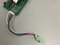
Aquire a modified OpenStorm relay board.
-
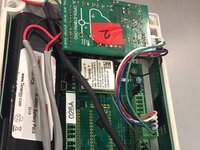
Ensure that the yellow-boxed resistor is removed.
-
Aquire an OpenStorm motherboard.
-
Attach an assigned and activated cellular modem, antenna, and GPS if not already attached.
-
-
-
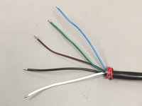
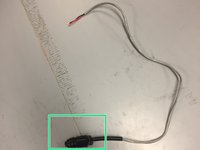
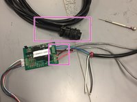
Strip the 6 pin connector wire;
-
Strip each of the 6 inner wires except for the red wire.
-
Move the red wire out of the way of the rest of the wires.
-
-
-
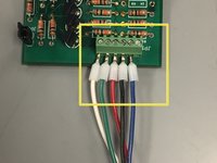
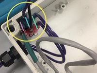
Using 5 different colored jumper wires connect the 6 pin connector on the node board to a 5 pin connector.
-
On the board, screw the jumpers into the terminals omitting the final terminal on the right.
-
In the order of (left to right): pulses to sampler (white), bottle count (green), power (red), ground (black), and event mark (blue).
-
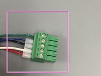
On the 5-pin connector, screw the jumpers into the terminal in the order of (bottom of screen to top): power (red), pulses to sampler (white), ground (black), event mark (blue), and bottle count (green).
-
-
-
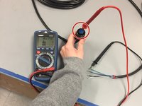
Determine which wire is connected to which pin using a multimeter on the resistance setting.
-
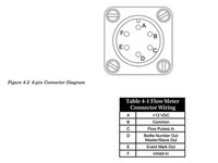
The pins as shown in figure 4-2 are the opposite of the pins circled in red. The figure is illustrating the pins as seen on the Autosampler rather than on the connector shown.
-
The wire colors as determined by this test for this wire configuration are as follows: blue = bottle number, green = pulses to autosampler, brown = event mark, black = power, white = ground, red = inhibit.
-
-
-
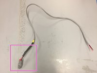
Pull the power(black) and ground(white) wires separate from the signal wires(all others).
-
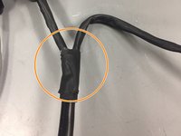
Cut the black casing down as done earlier to expose the wires for testing until the wires can reach through the entire node box.
-
Feed the two groups of wires for signaling and for power through two separate sheaths of heat shrink wrap.
-
Cover the joint with a larger section of heat shrink cable.
-
-
-
-
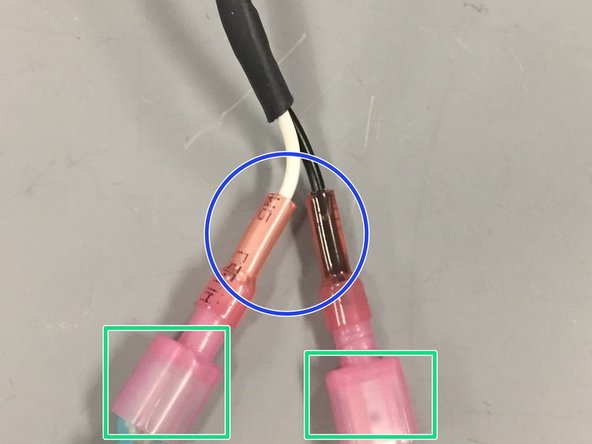
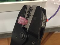
Aquire heat shrink female connectors.
-
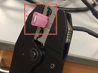
Crimp the heat shrink connectors at the point just below the widening on the power(black) and ground(white) wires of the 6-pin autosampler wire.
-
Use the heat gun to shrink the connector to touch the wire.
-
-
-
Aquire a 2-pin amphenol battery box connector, or refer to the Autosampler Node Assembly (For New Version) ifixit guide to create a new one. Male side used in node box and female side used in battery box.
-
Aquire a 2-pin amphenol connector, or refer to the Autosampler Battery Enclosure Assembly (For Old & New Versions) guide to create a new one.
-
-
-
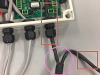
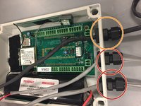
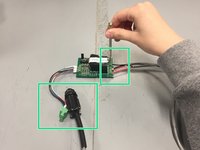
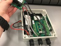
Pull the battery connection wires that go to the 2-pin amphenol battery box connectors through the middle port.
-
Pull the battery connection wires that go to the 2-pin amphenol autosampler batter connector through the bottom port.
-
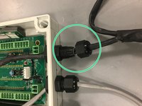
Pull only the portion of the autosampler wires through the top port that has the signal wires (e.g. the bottle count and pulses).
-
Twist the outer side of the port down until it fits snuggly around the wire.
-
-
-
Feed two power rated wires through the lower hole unconnected to any previously referred to wires.
-
Feed the female end of the battery amphenol connector through the upper hole.
-
Add male crimp connectors to the ends of the power rated wires and the battery amphenol connector wires that are inside the battery box.
-
Plug in the purple battery wires to the switch
-
Plug in the amphenol battery wires to the switch.
-
Take two more short power rated wires and add male crimps to both ends of the wires. One wire will connect to the ground of a battery and the other the power of the battery. Place a fuse in the center of the power wire.
-
Plug one side of the doubly male crimped wires into the switch.
-
-
-
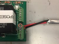
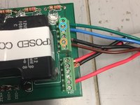
Take the two wires from the 2-pin female amphenol battery box connector and screw them into the board.
-
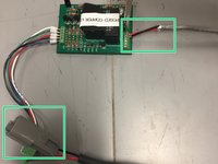
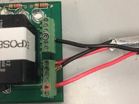
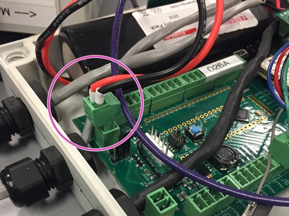
Screw the red power wire into the topmost terminal on the bottom 6-pin connector.
-
Screw the black ground wire into the terminal directly below the red wire.
-
-
-
Screw the red power and black ground wires into the board from the 2-pin amphenol connector that attaches directly to the sampler.
-
Screw the black ground wire into the terminal 2 up from the bottom terminal of the top connector.
-
Screw the red power wire into the terminal 1 up from the bottom of the bottom connector.
-
-
-
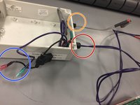
Attach the blue, green, and brown wires from the 6-pin connector to the board. These wires have been fed through the box previously and are heat shrink wrapped.
-
Screw the green wire into the topmost terminal on the top connector.
-
Screw the blue wire into the terminal directly below the green wire
-
Screw the brown wire into the terminal directly below the black wire on the top connector.
-
-
-
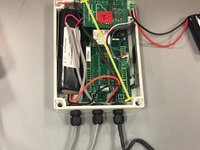
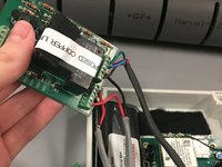
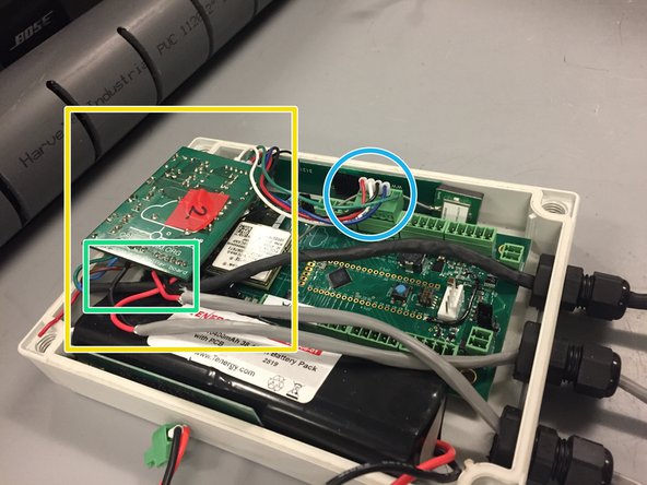
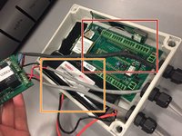
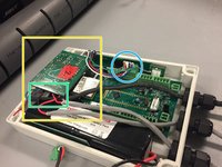
Slide the open storm board into the node box on the right pushed up as close to the ports as possible.
-
Slide the 3-4V battery into the enclosure on the left side.
-
Carefully fold the connected relay board over so that it fits within the enclosure snuggly.
-
Check to make sure that the connections remained secure.
-
Plug the 6 pin connector into the port on the open storm board that is the second from the left side of the board in the image near the SD card port.
-
Check that the battery port is exposed for deployment, but do not plug in the battery until the sampler is ready to begin sampling.
-


Équipe
